低損失材料 2026-2036年:市場、動向、予測Low-Loss Materials 2026-2036: Markets, Trends, and Forecasts 5G、6G、車載レーダー、高速デジタル向け低損失材料、市場評価、プレーヤー概要、トレンド、詳細ベンチマーク、予測を掲載。 通信システムの高周波化に伴い、伝送損失はますます大きくなり、... もっと見る

サマリー
5G、6G、車載レーダー、高速デジタル向け低損失材料、市場評価、プレーヤー概要、トレンド、詳細ベンチマーク、予測を掲載。
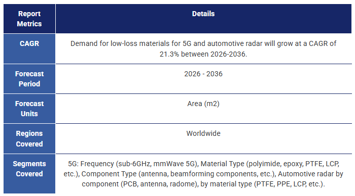
通信システムの高周波化に伴い、伝送損失はますます大きくなり、信号強度と完全性を維持するために低損失材料が不可欠となっている。このような材料は、5G mmWaveや2030年頃に展開が予想される将来の6G通信、先進運転支援システム(ADAS)用の自動車レーダーシステムなどの技術に不可欠である。同様に、データ・センター・インフラは200Gbpsを超える超高速データ・レートに移行しており、このような厳しい条件下で信頼性の高い性能を発揮し、シグナル・インテグリティを維持できる材料の必要性が高まっている。IDTechExの予測では、今後10年間で、5Gと車載レーダー向けの材料需要は年平均成長率(CAGR)21.3%で約7倍に増加する。
IDTechExのレポートは、低損失材料の需要を促進する主要技術と応用分野を調査し、市場動向の独立した包括的な分析を提供している。一次調査に基づき、業界動向の洞察、主要市場プレイヤーの分析、重要な材料性能特性にわたる製品のベンチマークを提供しています。また、アプリケーションと材料タイプ別に区分した10年間の需要予測も掲載しています。
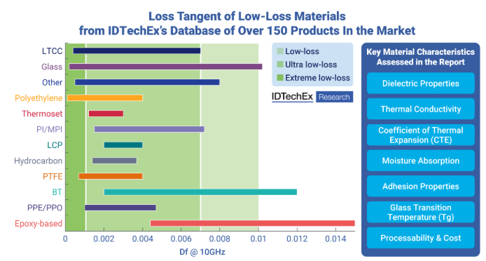
IDTechExのレポート「低損失材料 2026-2036」で評価されている低損失材料の損失正接(Df)値の範囲と主要材料特性。出典:IDTechEx
5G以降の低損失材料
今後のミリ波5G、ひいては6Gの台頭により、低損失材料は急速な成長を遂げ、ますます重要な役割を果たすことになる。低損失材料は、RF部品の基板やPCBとしてだけでなく、先進的なパッケージ内でも使用されるようになる。通信技術がmmWave 5Gやそれ以上へと高周波化するにつれて、アンテナ素子のサイズは縮小し、アレイをパッケージ自体に収めることができるようになる。この統合はまた、RF経路を短縮し、伝送損失を最小化するのに役立つ。AiPでは、基板、再配線層、電磁干渉(EMI)シールド、モールドアンダーフィル(MUF)材料などに低損失材料が必要になる。本レポートでは、5Gスマートフォン、基地局、CPE向けの周波数別(サブ6GHzおよびミリ波)、材料タイプ別(エポキシおよびBT、PTFE、LTCCおよびセラミックス、PIおよびMPIなど)の10年間の材料需要予測とともに、これらのトレンドと技術をより詳細に取り上げている。
さらに、IDTechExが2030年頃に商用化されると予想している6Gの準備作業も順調に進んでいる。研究機関や材料サプライヤーは、次世代の電気通信技術に対応するために必要な材料要件をすでに模索している。本レポートでは、6G向けにさらに低いDf/Dkを達成するためのアプローチと、再構成可能なインテリジェント表面(RIS)のような潜在的な6Gアプリケーションについて検討する。
車載レーダー用低損失材料
自動車の自律化が進むにつれ、各車両に組み込まれるセンサーの数は増加の一途をたどっている。過去10年間、高度化するADAS機能により、レーダー技術が広く採用されるようになり、現在では76~81GHz帯の長波長レーダーが採用され、140GHz帯のシステムも開発中である。このシフトと並行して、システム統合の進展や継続的なコスト圧力などの業界動向により、高周波数で確実に動作するコスト効率の高い低損失材料が重視されるようになっている。このようなニーズを満たすためには、材料は動作周波数と温度にわたって低くて安定した誘電率(Dk)と損失正接(Df)を示すだけでなく、コスト競争力を維持しながら、強い熱安定性と湿度安定性、一貫した物理的・電気的性能、高い製造加工性を実現する必要があります。本レポートでは、車載用レーダーのトレンド、材料要件、材料需要(材料タイプ別)の10年予測について詳細に評価しています。
高速デジタル向け低損失材料
シグナルインテグリティに対する要求は、接続が進む世界の増大するデータニーズに対応するために、より高い周波数とより速いデータ転送速度が不可欠になるにつれて高まり続けています。データセンター・インフラストラクチャでは、高性能コンピューティング・サーバ、ストレージ・エリア・ネットワーク、トランシーバ、ルータ、パワーアンプ、高速データチャネルなどの基板に低損失材料が使用され、高速データ転送速度のシグナルインテグリティと信頼性を維持するために、低損失材料への依存度が高まっている。高速デジタル(HSD)用基板は、一般に高密度のトレースを持つ多層複雑構造であるため、HSD用材料の選定には、製造中に何度も熱サイクルを受ける必要があることから、機械的および熱的特性を十分に考慮する必要がある。IDTechExは、このような用途にますます注力している京セラやIsolaなどの低損失材料メーカーに話を聞いた。
本レポートで取り上げた低損失材料のベンチマーク
IDTechExは本レポートで、低損失材料の状況を調査し、誘電率(Dk)、散逸係数/損失正接(Df)、誘電特性の周波数依存性、熱伝導率、熱膨張係数(CTE)、ガラス転移温度、吸湿率など、いくつかの重要な要素によって150以上の製品の性能をベンチマークしている。さらに、材料コストや加工性についても考察している。
有機材料は高周波用途で大きな人気を博しており、PTFEに代わる材料を見出そうと大きな努力が払われています。また、PPE、LCP、炭化水素、その他の高度な熱硬化性樹脂などの材料の採用も見られます。無機材料の進歩は遅いように見えるが、ガラス、LTCC、その他のセラミックなどの材料は、優れた電気的・熱的特性により、長期的に大きな可能性を秘めている。
本レポートでは、高周波用途に有望な低損失材料にスポットを当てている。これには、
主要な側面
本レポートは、5Gや6G、車載レーダー、高速デジタル(HSD)などの高周波アプリケーション向け低損失材料の主要材料、プレーヤー、動向に関する広範な情報と分析を提供する。
2025-2036年の10年間の粒度予測:
目次1.エグゼクティブサマリー
1.1.低損失材料の需要を牽引する高周波通信
1.2.低損失材料の主要動向と要件
1.3.用途別の代表的なDkとDf値の要件
1.4.本レポートで取り上げる低損失材料
1.5.半導体・電子機器パッケージにおける低損失材料の用途
1.6.低損失材料の需要を牽引するモバイル通信の進化
1.7.モバイル通信スペクトラムとネットワーク展開戦略
1.8.5G向け低損失材料のIDTechEx予測:材料タイプ別
1.9.LTCC:市場シフトとトレンド
1.10.6Gとは何か、なぜ開発するのか?
1.11.6G 向け低損失材料の IDTechEx 展望
1.12.高速デジタル向け低損失材料の用途
1.13.高速デジタル向け低損失材料の動向
1.14.レーダーは先進運転支援システム(ADAS)の重要なイネーブラー
1.15.車載レーダー用PCB材料の主要動向と要件
1.16.車載レーダー用PCBとアンテナ向け低損失材料のIDTechEx予測
1.17.有機高周波ラミネート材料の技術革新動向
1.18.高周波通信に不可欠な伝送損失の最小化
1.19.IDTechExの150製品データベースに基づく低損失材料の概要
1.20.ベンチマーク-150以上の低損失有機および無機材料のDk対Df
1.21.DkとDfの周波数依存性:有機および無機材料
1.22.低損失材料の選択において考慮すべきその他の重要な要素
1.23.比較:低損失材料のCTE
1.24.比較低損失材料のガラス転移温度
1.25.まとめ:吸湿性、熱伝導性、加工性、コスト
1.26.低損失材料のプレーヤー概要:材料タイプ別
1.27.予測:5G CPE、スマートフォン、インフラ、車載レーダー向け低損失材料分野
1.28.6G、車載レーダー、アンテナインパッケージの技術と市場に関する詳細は
1.29.IDTechEx サブスクリプションでさらにアクセス
2.はじめに
2.1.高周波通信が低損失材料の需要を牽引
2.2.高周波通信:課題、トレンド、イノベーション
2.3.低損失材料は高周波通信の鍵である
2.4.本レポートで取り上げる低損失材料
2.5.半導体・電子機器パッケージにおける低損失材料の応用
2.6.銅張積層板の構造
2.7.銅張積層板の主要部品
2.8.積層板の PCB コア:重要な側面
2.9.5G 用の低損失素材
2.10.低損失材料はレドーム・カバーや成形ハウジングにも使える
2.11.車載用ミリ波レーダー:77GHz帯
2.12.半導体パッケージおよび高速デジタル(HSD)用低損失材料
2.13.特許出願の動向
3.材料・プレーヤー
3.1.1.PCBおよび半導体パッケージ用低損失材料の概要
3.1.2.材料の概要:用途別
3.1.3.プレーヤーの概要:材料タイプ別
3.1.4.低損失材料の選択で考慮すべき重要な要素
3.1.5.まとめ:セラミックス対有機物
3.1.6.銅箔は?
3.1.7.誘電率の安定性はシグナルインテグリティにとって重要な考慮事項
3.1.8.リジッドフレックスとフレキシブルPCB:用途と規格
3.1.9.リジッドフレックスとフレキシブルPCB:タイプ
3.2.低損失有機ラミネートの概要
3.2.1.一般的なポリマーの電気特性
3.2.2.熱可塑性樹脂と熱硬化性樹脂の比較
3.2.3.5G向け熱可塑性樹脂と熱硬化性樹脂の比較
3.2.4.5G以降の有機PCB材料の進化
3.2.5.有機高周波ラミネート材料の技術革新動向
3.3低損失有機材料:設計上の考慮事項
3.3.1.低誘電損失を達成するための戦略とトレードオフ
3.3.2.誘電損失に影響する要因:分極率とモル体積
3.3.3誘電損失に影響する因子硬化温度
3.3.4.DkとDfを低減する戦略:低極性官能基
3.3.3.3.3.3.5.DkとDfを低減する戦略:添加剤
3.3.3.3.6.Dkを低減する戦略嵩高い構造
3.3.7.Dkを低減する戦略多孔質構造
3.3.8.Dfを低減する戦略硬い構造
3.3.9.まとめ:DkとDfを下げる主な戦略
3.3.10.ガラス/樹脂比の影響
3.3.3.3.11.誘電特性に及ぼす温度の影響
3.3.12.水分の影響
3.3.13.PCBフィーチャーサイズに対するDkと基板選択の影響
3.3.14.高周波用途におけるPCB-基板薄化の課題
3.4.低損失熱硬化性樹脂:プレーヤー
3.4.1.低損失熱硬化性樹脂サプライヤー味の素グループの味の素ビルドアップフィルム(ABF) (1/2)
3.4.2.味の素ビルドアップフィルム:ABFを用いた基板の製造工程
3.4.3.低損失サーモセットサプライヤー太陽インキのPPEベースのビルドアップ材料
3.4.4.低損失熱硬化性樹脂サプライヤーJSRの自己架橋型熱硬化性ポリエーテル
3.4.5.低損失熱硬化性樹脂のサプライヤーデュポン社のパイララックス・ラミネート
3.4.6.低損失熱硬化性樹脂のサプライヤーパナソニックのXPEDIONシリーズ
3.4.7.低損失熱硬化性樹脂のサプライヤーレゾナック
3.4.8.低損失熱硬化性樹脂のサプライヤー三菱ガス化学のBTラミネート
3.4.9.低損失熱硬化性ラミネートのサプライヤーイソラ
3.4.10.イソラの熱硬化性材料のポートフォリオ
3.4.11.低損失熱硬化性ラミネートのサプライヤーロジャース
3.4.12.低損失熱硬化性接着剤:東レのFALDA
3.4.13.低損失熱硬化性ラミネートのサプライヤー南雅プラスチック
3.5.低損失熱可塑性プラスチック液晶ポリマー
3.5.1.液晶ポリマー(LCP)
3.5.2.LCPの分類
3.5.3.フレキシブルプリント基板用PIの代替としてのLCP
3.5.4.LCPとPIの比較:DkとDf
3.5.5.LCPとPIの比較湿気
3.5.6.LCPとPIの比較柔軟性
3.5.7.LCP: コスト
3.5.8.液晶ポリマーのサプライチェーン
3.5.9.LCPサプライヤー住友化学
3.5.10.LCPサプライヤーセラニーズ
3.5.11.市販のLCPとLCP-FCCL製品
3.6.PTFEとPFA
3.6.1.フッ素樹脂とPTFE入門
3.6.2.考慮すべきPTFEの主な特性
3.6.3.PTFEベースの積層板の誘電特性に及ぼす結晶化度の影響
3.6.4.PTFE:加工中のPTFEの寸法不安定性
3.6.5.セラミック充填 PTFE ラミネートとガラス充填 PTFE ラミネート
3.6.6.セラミック/LTCCの5G応用分野
3.6.7.5GにおけるPTFEの主な用途
3.6.8.高周波 5G に PTFE ベースの積層板を使用することの懸念
3.6.9.PTFE ラミネートのサプライヤーロジャース
3.6.10.PTFEラミネートのサプライヤーロジャース (2)
3.6.11.PTFEラミネートのサプライヤーAMMK / AGC
3.6.12.PTFEラミネートのサプライヤーSYTECH
3.6.13.PFAラミネートのサプライヤーケムール
3.7.低損失素材における持続可能性:PTFE
3.7.1.PFASの紹介
3.7.2.PFASの悪影響に対する懸念の高まり
3.7.3.PFAS規制の見通し:EU
3.7.4.PFASの規制見通し:米国
3.7.5.低損失材料に関連するPFASに関する規制
3.7.6.PFASに関する詳細情報
3.8.その他の有機材料PPE、PPS、PBT、炭化水素など
3.8.1.ポリ(p-フェニレンオキシド)(PPO):サビック
3.8.2.ポリパラフェニレンエーテル(PPE)パナソニックのMEGTRONシリーズ
3.8.3.AGCの車載、5G、チップ、HSD向けPPEレンジCCL
3.8.4.変性ポリ(p-フェニレンエーテル)(mPPE):旭化成のザイロン(1)
3.8.5.変性ポリ(p-フェニレンエーテル)(mPPE):旭化成キシロン(2)
3.8.6.変性ポリ(p-フェニレンエーテル)(mPPE):旭化成「サンフォース」
3.8.7.ポリフェニレンスルフィド(PPS):ソルベイ社の基地局アンテナ用材料
3.8.8.ポリブチレンテレフタレート(PBT):東レ
3.8.9.炭化水素系積層板
3.8.10.ポリカーボネート(PC)コベストロの射出成形筐体・カバー用材料
3.8.11.レアード社のレドーム、アンテナスペーサー、PCB、その他部品用ECCOSTOCKシリーズ
3.8.12.エアロゲル・サプライヤーブルーシフト社のポリイミド・エアロゲル・ラミネート用AeroZero
3.9.低温同時焼成セラミックス(LTCC)とセラミックス
3.9.1.セラミック材料、HTTC、LTTCの紹介
3.9.2.LTCCサブステート製造プロセス
3.9.3.さまざまな市販LTCC基板のDkとDf
3.9.4.LTCC:プレーヤーの概要
3.9.5.LTCCのサプライヤーセラニーズ
3.9.6.LTCCサプライヤー日本電気硝子(NEG)
3.9.7.LTCCサプライヤー日本電気硝子のGCコア
3.9.8.LTCCサプライヤー京セラ
3.9.9.LTCCサプライヤー京セラのLTCCベースパッケージ
3.9.10.LTCC:利点と課題
3.10.ガラス
3.10.1.ガラス基板
3.10.2.ガラス基板の特性
3.10.3.強化材としてのガラス-低Dkガラスと石英への移行
3.10.4.有機物用ガラス強化繊維
3.10.5.有機物用強化ガラス-Eガラスの課題
3.10.6.ショットの低損失ガラス基板
3.10.7.溶融シリカ
3.10.8.日本板硝子有機ガラス用フィラー
3.11. 6G向け材料
3.11.1. 5Gと6Gの技術革新の比較
3.11.2. IDTechExによる6G向け低損失材料の展望
3.11.3. 1THzにおける各種材料の誘電率(Dk)と誘電率(Df)
3.11.4. 6G向けポリイミド材料の試験
3.11.5.市販のロジャースLCP、セラミック充填PTFE材料の試験
3.11.6.6G用RDL材料
3.11.7.6G用熱可塑性プラスチック:ジョージア工科大学
3.11.8.6G用PTFE:延世大学、GIST
3.11.9.6G用PPS:四川大学
3.11.10.6G用熱硬化性樹脂:ITEQ、INAOE
3.11.11.6G用PPE:太陽インキ、ジョージア工科大学
3.11.12.6G用シリケート材料:オウル大学、セゲド大学
3.11.13.6G用シリケート材料:東京工業大学、AGC
3.11.14.6G用ガラス:ジョージア工科大学
3.11.15.6G用ガラスインターポーザー
3.11.16.メタマテリアル - 概要
3.11.17.LCPは、アクティブなメタサーフェスを作る有望な方法である
3.11.18.アルキャン・システムズ、透明液晶フェーズドアレイアンテナを開発
3.11.19.メタマテリアルに関する詳細情報
4.PCB および RF コンポーネント用市販低損失材料のベンチマーク
4.1.1.アプリケーション別に要求される典型的なDk値とDf値
4.1.2.150 種以上の有機、無機、複合低損失材料のベンチマーク - Dk 対 Df
4.1.3.Dk と Df の周波数依存性:有機材料と無機材料
4.1.4.低損失材料の吸湿率
4.1.5.低損失材料の熱伝導率
4.1.6.低損失材料のCTE
4.1.7.低損失材料のガラス転移温度
4.2.有機材料
4.2.1.有機材料のDk vs Df (1)
4.2.2.有機材料のDk対Df(2)
4.2.3.利点と課題:素材タイプ別
4.2.4.有機材料:例と典型的なアプリケーション
4.2.5.DkとDfの周波数依存性:PPE材料
4.2.6.DkとDfの周波数依存性:その他の有機材料
4.2.7.低損失有機材料のその他の関連特性-平均値
4.2.8.有機材料の種類別熱伝導率
4.2.9.有機材料タイプ別積層板のピール強度
4.2.10.有機材料の種類別ガラス転移温度(Tg)
4.2.11.熱膨張係数(CTE)-T<Tg
4.3.無機材料
4.3.1.ベンチマークLTCCのDkとDf
4.3.2.LTCC材料-熱伝導率とCTE
4.3.3.ベンチマークガラス材料
4.3.4.DkとDfの周波数依存性:無機材料
4.4.複合材料
4.4.1.炭化水素材料と複合材料(1)
4.4.2.炭化水素材料の比較:DkとDf
4.4.3.炭化水素材料の比較CTE
4.4.4.炭化水素材料の比較熱伝導率と吸湿率
4.4.5.PTFE材料の比較-DkとDf
4.4.6.PTFE材料の比較-熱伝導率と吸湿率
4.5.低損失材料のまとめ
4.5.1.5G、6G、THz PCB/部品用市販低損失材料の現状と展望
4.5.2.材料の比較
5.半導体パッケージングの動向
5.1.1.先端半導体パッケージングの概要
5.1.2.1Dから3Dへの半導体パッケージングの進展
5.1.3.5Gおよび6Gコネクティビティ向けパッケージング動向
5.1.4.6G用アンテナモジュールの設計動向
5.1.5.集積技術のトレードオフ
5.2.アンテナ・パッケージング
5.2.1.アンテナパッケージと動作周波数
5.2.2.mmWaveアンテナ統合の3つの方法
5.2.3.アンテナパッケージング技術オプションの選択
5.2.4.つのアンテナパッケージング技術のベンチマーク
5.2.5.次世代フェーズドアレイターゲット
5.2.6.高周波集積とパッケージングのトレンド
5.2.7.低損失材料:5G mmWave AiPの鍵
5.2.8.有機材料:AiP における基板の主流選択
5.2.9.5G 向け LTCC AiP:TDK
5.2.10.AiP向け基板技術のベンチマーク
5.2.11.mmWaveにおけるアンテナ統合の課題
5.2.12.6G向けアンテナ・オンチップ(AoC)
5.2.13.5Gから6Gへのハードウェア・コンポーネントの進化
5.2.14.周波数>100 GHzにおけるパッケージングの課題
5.2.15.5Gおよび6G向けAiP、2024~2034年
5.3.パッケージ・レベルでの低損失材料
5.3.1.5G mmWave AiP向け低損失材料の選択
5.3.2.AiP 向け低損失材料のベンチマーク
5.3.3.2 種類の IC 内蔵技術
5.3.4.2種類のIC内蔵技術
5.3.5.技術タイプ別IC組み込み技術の主要市場プレイヤー
5.3.6.EMCとMUFとは?
5.3.7.エポキシモールディングコンパウンド(EMC)
5.3.8.EMCとEMCフィラーの主要パラメーター
5.3.9.低誘電率のEMC実験品と市販品
5.3.10.エポキシ樹脂:各種樹脂と硬化剤系のパラメータ
5.3.11.EMC材料のサプライチェーン
5.3.12.高周波用途のEMC技術革新動向
5.3.13.モールドアンダーフィル(MUF)
5.3.14.液状成形コンパウンド(LMC)
5.4.ウェハーレベルの低損失材料
5.4.1.再分配層(RDL)
5.4.2.次世代2.5Dファンアウトパッケージング用有機RDL材料の主要パラメータ
5.4.3.有機 RDL の業界プレーヤー
5.4.4.さまざまなパッケージング技術における低損失 RDL 材料の重要性
5.4.5.mmWave向け低損失RDL材料:TSMCのInFO AiP
5.4.6.まとめ:有機 RDL 技術の開発動向
5.4.7.先端半導体パッケージ向け材料の詳細については
6. 5G/6G 通信
6.1.1.モバイル通信の進化
6.1.2.2G から 6G へのスペクトラム特性
6.1.3.モバイル通信スペクトラムとネットワーク展開戦略
6.1.4.進化するモバイル通信の焦点
6.1.5.加速する5G展開
6.1.6.5G展開からの教訓
6.1.7.6Gとは何か?
6.1.8.IMT-2030の強化された性能要件
6.1.9.6G スペクトラム - どの帯域が検討されるか?
6.1.10.6G - 主要アプリケーションの概要
6.1.11.6G 展開スケジュール
6.1.12.6G 産業の最新情報 - ベンダー
6.2.技術
6.2.1.アンテナのサイズは周波数の増加とともに縮小
6.2.2.5Gにおける主な技術革新
6.2.3.5G基地局のタイプ:マクロセルとスモールセル
6.2.4.マッシブMIMO(mMIMO)
6.2.5.マッシブMIMO(mMIMO)システムの構造
6.2.6.無線通信におけるMIMOの進化
6.2.7.なぜセルフリーMIMOなのか
6.2.8.mmWave 5Gに適合するフィルター技術
6.2.9.mmWave 5Gアプリケーションのための選択されたフィルター技術のベンチマーク
6.2.10.5G mmWave 向け伝送ライン・フィルターの概要
6.2.11.伝送線路フィルターの材料
6.2.12.2GからmmWave 5Gへのスマートフォンアンテナの進化
6.2.13.RIS - 概要
6.2.14.RISの動作周波数
6.2.15.6G市場の詳細については
7.車載レーダー
7.1.1.車載レーダーの概要
7.1.2.自律走行車がレーダーの成長を牽引する
7.1.3.レーダーは最新の ADAS 機能の主要部分
7.1.4.パッケージングと統合の動向
7.1.5.周波数はどちらに向かうのか?
7.1.6.異なる周波数のアプリケーション
7.1.7.周波数別アプリケーション(2)
7.1.8.自動車用レーダーの周波数動向
7.1.9.高周波レーダーの採用経路
7.1.10.パッケージングの利点
7.2.コンポーネントと材料
7.2.1.レーダー解剖学
7.2.2.レーダーの主要部品 - アンテナ
7.2.3.理想的なレドームの特性
7.2.4.プリパーム
7.2.5.レアード - サイドローブ低減スカートの材質
7.2.6.その他の材料に関する考察
7.2.7.車載用レーダーの主なトレンド
7.2.8.車載レーダー用PCB材料の主な要件
7.2.9.車載レーダー向け低損失材料サプライヤーの状況
7.2.10.車載レーダー用基板として市販されている低損失基板
7.2.11.車載レーダー市場に関する詳細は
8.高速デジタル
8.1.1.高速デジタル用PCBの用途
8.1.2.データセンターはHSD材料需要の主要な原動力
8.1.3.データセンター設備 - トップレベルの概要
8.1.4.データセンターのサーバーラックとサーバー構造
8.1.5.波形:HSD 対 RF および材料要件
8.1.6.データセンターと AI の帯域幅と周波数要件のロードマップ
8.1.7.HSD に対する Dk と Df 要件の動向
8.1.8.AGC の HSD 基板用低損失材料
8.1.9.その他の市販低損失基板 HSD基板
8.1.10.高速基板のロードマップ (1/3)
8.1.11.高速基板ロードマップ (2/3)
8.1.12.高速基板のロードマップ (2/3)
9.予測
9.1.1.予測5G CPE、スマートフォン、インフラ、車載レーダー向け低損失材料分野
9.2.5G 向け低損失材料予測
9.2.1.予測方法と範囲:5G
9.2.2.5G向け低損失材料分野:市場セグメント別
9.2.3.5G向け低損失材料:材料タイプ別、周波数別
9.3.5Gインフラ向け低損失材料の予測
9.3.1.5G 基地局用低損失材料:周波数別
9.3.2.5G 基地局用低損失材料:材料タイプ別
9.3.3.5G 基地局用低損失材料の部品タイプ別セグメント化
9.4.5Gスマートフォン向け低損失材料の予測
9.4.1.周波数別に見た5G スマートフォン向け低損失材料
9.4.2.5G スマートフォン向け低損失材料の材料タイプ別
9.5.5G CPE向け低損失材料の予測
9.5.1.周波数別 5G CPE 向け低損失材料
9.5.2.5G CPE向け低損失材料の材料タイプ別予測
9.6.車載レーダー用低損失材料の予測
9.6.1.予測方法と範囲:車載レーダー
9.6.2.車載用レーダーの低損失材料:部品別
9.6.3.車載レーダー向け低損失材料の市場予測材料タイプ別
9.6.4.前回予測との比較:2024 年版と 2026 年版の 5G 向け比較
10.企業プロファイル
10.1.IDTechExポータルを通じた企業プロファイルへのアクセス

Summary
Low-loss materials for 5G, 6G, automotive radars, high-speed digital, with market assessment, player overview, trends, detailed benchmarks, and forecasts.
Transmission losses become increasingly significant as communication systems move toward higher frequencies, making low-loss materials essential to preserve signal strength and integrity. These materials are critical for technologies such as 5G mmWave and future 6G telecommunications which is expected to see deployment around 2030, as well as for automotive radar systems for advanced driver assistance systems (ADAS). Similarly, data center infrastructure is shifting toward ultra-high data rates exceeding 200Gbps amplifying the need for materials that can perform reliably and maintain signal integrity under such demanding conditions. The growth of these markets presents a significant opportunity for low-loss materials, with IDTechEx's forecasts predicting a ~7-fold increase in material demand for 5G and automotive radar over the next decade, at a CAGR of 21.3%.
IDTechEx's report offers an independent and comprehensive analysis of market trends, examining key technologies and application areas driving demand for low-loss materials. Drawing on primary research, the report delivers insights into industry developments, analyzes leading market players, and benchmarks products across critical material performance characteristics. The report also includes 10-year demand forecasts segmented by application and material type.
The range of loss tangent (Df) values of low-loss materials and the key material properties assessed in IDTechEx's report Low-Loss Materials 2026-2036. Source: IDTechEx
Low-Loss Materials for 5G and Beyond
With the future rise of mmWave 5G and eventually 6G, low-loss materials will experience rapid growth and play an increasingly important role. Low-loss materials will not only be used as a substrate for RF components or for the PCB, but also within advanced packages. One strong packaging trend is antenna in package (AiP); as telecom technology goes higher in frequency towards mmWave 5G and beyond, the size of the antenna elements will shrink such that the arrays can be fitted into the package itself. This integration will also help shorten the RF paths and thus minimize the transmission losses. AiP will need low-loss materials for the substrates, redistribution layers, electromagnetic interference (EMI) shielding, mold underfill (MUF) materials, and more. The report covers these trends and technologies in greater detail, along with providing 10-year material demand forecast by frequency (sub-6GHz and mmWave) and material type (e.g. epoxy and BT, PTFE, LTCC & ceramics, PI & MPI, etc.) for 5G smartphones, base stations, and customer premise equipment (CPE).
Additionally, work is well underway in preparation for 6G which IDTechEx expects to enter commercialization around 2030. Research institutions and materials suppliers are already exploring the material requirements needed to meet the next generation of telecommunication technologies. This report explores the approaches to achieve even lower Df/Dk for 6G and potential 6G applications, like reconfigurable intelligent surfaces (RIS).
Low-Loss Materials for Automotive Radar
As automotive autonomy advances, the number of sensors integrated into each vehicle continues to rise. Over the past decade, increasingly sophisticated ADAS capabilities have driven widespread adoption of radar technologies, with the current 76-81GHz band for long-rage radar, and ongoing development of 140GHz systems. Alongside this shift, industry trends such as greater system integration and continual cost pressures are placing increased emphasis on cost-efficient, low-loss materials capable of operating reliably at high frequencies. To meet these needs, materials must not only exhibit low and stable dielectric constant (Dk) and loss tangent (Df) across operating frequencies and temperatures, but also deliver strong thermal and moisture stability, consistent physical and electrical performance, and high manufacturing processability, all while keeping costs competitive. Detailed assessments of trends, material requirements, and 10-year forecasts for material demand (by material type) for automotive radar are available within the report.
Low-Loss Materials for High-Speed Digital
The demand for signal integrity continues to rise as higher frequencies and faster data transfer speeds become essential to meet the growing data needs of our increasingly connected world. Datacenter infrastructure increasingly relies on low-loss materials to maintain signal integrity and reliability for high data transfer rates, where low-loss materials are used in substrates across high performance computing servers, storage area networks, transceivers, routers, power amplifiers, high speed data channels, and more. Substrates for high-speed digital (HSD) are generally multilayered complex structures with high density of traces, thus selecting materials for HSD requires significant consideration of the mechanical and thermal properties as these need to undergo multiple thermal cycling during manufacturing. IDTechEx spoke to low-loss materials players such as Kyocera and Isola, who are increasingly focusing on these applications.
Benchmarks for Low-Loss Materials Covered within the Report
In this report, IDTechEx surveys the landscape of low-loss materials and benchmark the performance of over 150 products by several key factors, i.e. dielectric constant (Dk), dissipation factor/loss tangent (Df), frequency dependence of dielectric properties, thermal conductivity, coefficient of thermal expansion (CTE), glass transition temperature, moisture absorption, and more. In addition, the report also considers material cost and processability.
Organic materials have gained significant popularity for high frequency applications, with significant efforts to find PTFE alternatives, which has also seen the adoption of materials like PPE, LCP, hydrocarbons, and other advanced thermosets. While inorganic materials may appear to be progressing more slowly, materials like glass, LTCC, and other ceramics offer strong long-term potential owing to their excellent electrical and thermal properties.
The report highlights promising low-loss materials for high frequency applications. This includes
Key Aspects:
This report provides extensive information and analysis on the major materials, players, and trends for low-loss materials for high frequency applications such as 5G and 6G, automotive radar, and high-speed digital (HSD). It includes insights and analysis on:
The report provides 10-year granular forecasts 2025-2036:
Table of Contents1. EXECUTIVE SUMMARY
1.1. High Frequency Communications Driving Demand for Low-Loss Materials
1.2. Key Trends and Requirements for Low-Loss Materials
1.3. Typical Dk And Df Value Requirements by Applications
1.4. Low-loss materials discussed in this report
1.5. Applications of Low-loss Materials in Semiconductor and Electronics Packaging
1.6. Evolution OF Mobile Communications Driving Demand For Low-loss Materials
1.7. Mobile Telecommunication Spectrum and Network Deployment Strategy
1.8. IDTechEx Forecasts for Low-Loss Materials For 5G: By Material Type
1.9. LTCC: Market shifts and trends
1.10. What Is 6G And Why Develop It?
1.11. IDTechEx Outlook Of Low-Loss Materials For 6G
1.12. Applications of Low-Loss Materials for High-Speed Digital
1.13. Trends in Low-Loss Materials for High-Speed Digital
1.14. Radar is a Key Enabler for Advanced Driver Assistance Systems (ADAS)
1.15. Key Trends and Requirements for PCB Materials for Automotive Radar
1.16. IDTechEx Forecasts for Low-Loss Materials for Automotive Radar PCBs and Antenna
1.17. Innovation Trends for Organic High Frequency Laminate Materials
1.18. Minimizing Transmission Loss Essential in High Frequency Communication
1.19. Summary of Low-Loss Materials Based on IDTechEx's Database of 150 Products
1.20. Benchmark - Dk Vs Df of Over 150 Low-loss Organic and Inorganic Materials
1.21. Frequency Dependency Of Dk And Df: Organic and Inorganic Materials
1.22. Other Important Factors to Consider for the Selection of Low-Loss Materials
1.23. Comparison: CTE of Low-Loss Materials
1.24. Comparison: Glass Transition Temperature of Low-Loss Materials
1.25. Summary: Moisture Absorption, Thermal Conductivity, Processability, And Cost
1.26. Player Overview of Low-Loss Materials: By Material Type
1.27. Forecasts: Low-loss Materials Area for 5G CPE, Smartphones, Infrastructure, and Automotive Radar
1.28. For more information on 6G, automotive radar, and antenna-in-package technologies and markets
1.29. Access more with an IDTechEx subscription
2. INTRODUCTION
2.1. High Frequency Communications Driving Demand for Low-Loss Materials
2.2. High frequency communication: Challenges, trends, and innovation
2.3. Low-loss materials are key to high frequency communication
2.4. Low-loss materials discussed in this report
2.5. Applications of low-loss materials in semiconductor and electronics packaging
2.6. Anatomy of a copper clad laminate
2.7. Key components of copper clad laminates
2.8. PCB core in laminates: Key aspects
2.9. Low-loss materials for 5G
2.10. Low-loss materials can also be used in radome cover or molding housing
2.11. Automotive mmWave radars: 77GHz band
2.12. Low-loss materials for semiconductor packages and high-speed digital (HSD)
2.13. Trends and developments in patent applications
3. MATERIALS & PLAYERS
3.1.1. Overview of low-loss materials for PCBs and semiconductor packages
3.1.2. Material overview: By application
3.1.3. Player overview: By material type
3.1.4. Important factors to consider for the selection of low-loss materials
3.1.5. Summary: Ceramics vs Organics
3.1.6. What about the copper foil?
3.1.7. Stability of dielectric constant is a key consideration for signal integrity
3.1.8. Rigid-flex and flexible PCBs: Applications and standards
3.1.9. Rigid-flex and flexible PCBs: Types
3.2. Low-loss Organic Laminate Overview
3.2.1. Electric properties of common polymers
3.2.2. Thermoplastics vs thermosets
3.2.3. Thermoplastics vs thermosets for 5G
3.2.4. Evolution of organic PCB materials for 5G and beyond
3.2.5. Innovation trends for organic high frequency laminate materials
3.3. Low-Loss Organics: Design Considerations
3.3.1. Strategies to achieve lower dielectric loss and trade-offs
3.3.2. Factors affecting dielectric loss: Polarizability and molar volume
3.3.3. Factors affecting dielectric loss: Curing temperature
3.3.4. Strategies to reduce Dk and Df: Low polarity functional groups
3.3.5. Strategies to reduce Dk and Df: Additives
3.3.6. Strategies to reduce Dk: Bulky structures
3.3.7. Strategies to reduce Dk: Porous structures
3.3.8. Strategies to reduce Df: Rigid structures
3.3.9. Summary: Key strategies to lower Dk and Df
3.3.10. Impact of glass-to-resin ratio
3.3.11. Effect of temperature on dielectric properties
3.3.12. Moisture effects
3.3.13. The influence of Dk and substrate choice on PCB feature size
3.3.14. The challenge of thinning the PCB-substrate for high frequency applications
3.4. Low-Loss Thermosets: Players
3.4.1. Low-loss thermoset suppliers: Ajinomoto Group's Ajinomoto Build Up Film (ABF) (1/2)
3.4.2. Ajinomoto Build Up Film: Process for manufacturing substrates with ABF
3.4.3. Low-loss thermoset suppliers: Taiyo Ink's PPE-based build-up materials
3.4.4. Low-loss thermoset suppliers: JSR's self crosslinking thermoset polyether
3.4.5. Low-loss thermoset suppliers: DuPont's Pyralux laminates
3.4.6. Low-loss thermoset suppliers: Panasonic's XPEDION series
3.4.7. Low-loss thermoset suppliers: Resonac
3.4.8. Low-loss thermoset suppliers: Mitsubishi Gas Chemical's BT laminate
3.4.9. Low-loss thermoset laminate suppliers: Isola
3.4.10. Isola's portfolio of thermoset materials
3.4.11. Low-loss thermoset laminate suppliers: Rogers
3.4.12. Low-loss thermoset adhesive: Toray's FALDA
3.4.13. Low-loss thermoset laminate suppliers: Nan Ya Plastics
3.5. Low-loss thermoplastics: Liquid crystal polymers
3.5.1. Liquid crystal polymers (LCP)
3.5.2. LCP classification
3.5.3. LCP as an alternative to PI for flexible printed circuit boards
3.5.4. LCP vs PI: Dk and Df
3.5.5. LCP vs PI: Moisture
3.5.6. LCP vs PI: Flexibility
3.5.7. LCP: Cost
3.5.8. Liquid crystal polymer supply chain
3.5.9. LCP Supplier: Sumitomo Chemical
3.5.10. LCP Suppliers: Celanese
3.5.11. Commercial LCP and LCP-FCCL products
3.6. PTFE and PFA
3.6.1. An introduction to fluoropolymers and PTFE
3.6.2. Key properties of PTFE to consider
3.6.3. Effect of crystallinity on the dielectric properties of PTFE-based laminates
3.6.4. PTFE: Dimensional instability of PTFE during processing
3.6.5. Ceramic-filled vs glass-filled PTFE laminates
3.6.6. 5G application areas for ceramics/LTCC
3.6.7. Key applications of PTFE in 5G
3.6.8. Concerns of using PTFE-based laminates for high frequency 5G
3.6.9. PTFE laminate suppliers: Rogers
3.6.10. PTFE laminate suppliers: Rogers (2)
3.6.11. PTFE laminate suppliers: AMMK / AGC
3.6.12. PTFE laminate suppliers: SYTECH
3.6.13. PFA laminate suppliers: Chemours
3.7. Sustainability in low-loss materials: PTFE
3.7.1. Introduction to PFAS
3.7.2. Growing concerns about the negative impact of PFAS
3.7.3. Regulatory outlook for PFAS: EU
3.7.4. Regulatory outlook for PFAS: USA
3.7.5. Regulations on PFAS as relevant to low-loss materials
3.7.6. For more information on PFAS
3.8. Other organic materials: PPE, PPS, PBT, Hydrocarbons, etc
3.8.1. Poly(p-phenylene oxide) (PPO): Sabic
3.8.2. Poly(p-phenylene ether) (PPE): Panasonic's MEGTRON series
3.8.3. AGC's PPE range CCLs for automotive, 5G, chips, and HSD
3.8.4. Modified poly(p-phenylene ether) (mPPE): Asahi Kasei's XYRON (1)
3.8.5. Modified poly(p-phenylene ether) (mPPE): Asahi Kasei's XYRON (2)
3.8.6. Modified poly(p-phenylene ether) (mPPE): Asahi Kasei's SunForce
3.8.7. Polyphenylene sulfide (PPS): Solvay's materials for base station antennas
3.8.8. Polybutylene terephthalate (PBT): Toray
3.8.9. Hydrocarbon-based laminates
3.8.10. Polycarbonate (PC): Covestro's materials for injection-molded enclosures and covers
3.8.11. Laird's ECCOSTOCK range for radomes, antenna spacers, PCBs and other components
3.8.12. Aerogel suppliers: Blueshift's AeroZero for polyimide aerogel laminates
3.9. Low-temperature co-fired ceramics (LTCC) and ceramics
3.9.1. Introduction to ceramic materials, HTTC, and LTTC
3.9.2. LTCC substate manufacturing process
3.9.3. Dk and Df of different commercially available LTCC substrates
3.9.4. LTCC: Player overview
3.9.5. LTCC supplier: Celanese
3.9.6. LTCC Supplier: Nippon Electric Glass (NEG)
3.9.7. LTCC Supplier: GC Core by Nippon Electric Glass (NEG)
3.9.8. LTCC supplier: Kyocera
3.9.9. LTCC suppliers: Kyocera's LTCC-based packages
3.9.10. LTCC: Advantages and Challenges
3.10. Glass
3.10.1. Glass substrate
3.10.2. Properties of glass substrates
3.10.3. Glass as reinforcements - transition towards low Dk glass and quartz
3.10.4. Glass reinforcement weaves for organics
3.10.5. Glass as reinforcements for organics - challenges with E-glass
3.10.6. SCHOTT's low-loss glass substrates
3.10.7. Fused silica
3.10.8. Nippon Sheet Glass: Glass fillers for organics
3.11. Materials for 6G
3.11.1. Technical innovation comparison between 5G and 6G
3.11.2. IDTechEx outlook of low-loss materials for 6G
3.11.3. Dk and Df of various materials at 1THz
3.11.4. Testing of polyimide materials for 6G
3.11.5. Testing of commercially available Rogers' LCP, ceramic filled PTFE materials
3.11.6. RDL materials for 6G
3.11.7. Thermoplastics for 6G: Georgia Tech
3.11.8. PTFE for 6G: Yonsei University, GIST
3.11.9. PPS for 6G: Sichuan University
3.11.10. Thermosets for 6G: ITEQ Corporation, INAOE
3.11.11. PPE for 6G: Taiyo Ink, Georgia Institute of Technology
3.11.12. Silicate materials for 6G: University of Oulu, University of Szeged
3.11.13. Silicate materials for 6G: Tokyo Institute of Technology, AGC
3.11.14. Glass for 6G: Georgia Tech
3.11.15. Glass interposers for 6G
3.11.16. Metamaterials - Overview
3.11.17. LCPs are a promising method for creating active metasurfaces
3.11.18. Alcan Systems develops transparent liquid crystal phased array antennas
3.11.19. More information about Metamaterials
4. BENCHMARKING OF COMMERCIAL LOW-LOSS MATERIALS FOR PCBS AND RF COMPONENTS
4.1.1. Typical Dk and Df values requirements by applications
4.1.2. Benchmark - Dk vs Df of over 150 low-loss organic, inorganic & composite materials
4.1.3. Frequency dependency of Dk and Df: Organic and Inorganic Materials
4.1.4. Moisture absorption of low-loss materials
4.1.5. Thermal conductivity of low-loss materials
4.1.6. CTE of low-loss materials
4.1.7. Glass transition temperature of low loss materials
4.2. Organic Materials
4.2.1. Dk vs Df of organic materials (1)
4.2.2. Dk vs Df of organic materials (2)
4.2.3. Advantages and Challenges: By Material Type
4.2.4. Organic materials: Examples and typical applications
4.2.5. Frequency dependency of Dk and Df: PPE Materials
4.2.6. Frequency dependency of Dk and Df: Other Organic Materials
4.2.7. Other relevant properties of low-loss organic materials - average values
4.2.8. Thermal conductivity by type of organic material
4.2.9. Peel strength of laminates by organic material type
4.2.10. Glass transition temperature (Tg) by organic material type
4.2.11. Coefficient of thermal expansion (CTE) - T<Tg
4.3. Inorganic Materials
4.3.1. Benchmark: Dk and Df of LTCC
4.3.2. LTCC Materials - thermal conductivity and CTE
4.3.3. Benchmark: Glass materials
4.3.4. Frequency dependency of Dk and Df: Inorganics
4.4. Composites
4.4.1. Hydrocarbon materials and composites (1)
4.4.2. Hydrocarbon materials comparison: Dk and Df
4.4.3. Hydrocarbon materials comparisons: CTE
4.4.4. Hydrocarbon materials comparisons: Thermal Conductivity and Moisture Absorption
4.4.5. PTFE materials comparisons - Dk and Df
4.4.6. PTFE materials comparisons - Thermal Conductivity and Moisture Absorption
4.5. Summary of low-loss materials
4.5.1. Status and outlook of commercial low-loss materials for 5G, 6G, and THz PCBs/ components
4.5.2. Material Comparisons
5. TRENDS IN SEMICONDUCTOR PACKAGING
5.1.1. Overview of advanced semiconductor packaging
5.1.2. Progression From 1D To 3D Semiconductor Packaging
5.1.3. Packaging trends for 5G and 6G connectivity
5.1.4. Antenna Module Design Trends for 6G
5.1.5. Trade-Off in Integration Technologies
5.2. Antenna Packaging
5.2.1. Antenna Packaging vs Operational Frequency
5.2.2. Three ways of mmWave antenna integration
5.2.3. Choice of Antenna Packaging Technology Options
5.2.4. Benchmarking Three Antenna Packaging Technologies
5.2.5. Next Generation Phased Array Targets
5.2.6. High frequency integration and packaging trend
5.2.7. Low loss materials: Key for 5G mmWave AiP
5.2.8. Organic materials: The mainstream choice for substrates in AiP
5.2.9. LTCC AiP for 5G: TDK
5.2.10. Benchmark of Substrate Technologies for AiP
5.2.11. Antenna Integration Challenges in mmWave
5.2.12. Antenna on Chip (AoC) for 6G
5.2.13. Evolution of Hardware Components from 5G to 6G
5.2.14. Packaging Challenges for Freq. >100 GHz
5.2.15. mmWave AiP ecosystem
5.2.16. AiP for 5G and 6G, 2024-2034
5.3. Low-Loss Materials at the Package Level
5.3.1. Choices of low-loss materials for 5G mmWave AiP
5.3.2. Benchmark of low loss materials for AiP
5.3.3. Two types of IC-embedded technology
5.3.4. Two types of IC-embedded technology
5.3.5. Key market players for IC-embedded technology by technology type
5.3.6. What are EMC and MUFs?
5.3.7. Epoxy Molding Compound (EMC)
5.3.8. Key parameters for EMCs and EMC fillers
5.3.9. Experimental and commercial EMC products with low dielectric constant
5.3.10. Epoxy resin: Parameters of different resins and hardener systems
5.3.11. Supply chain for EMC materials
5.3.12. EMC innovation trends for high frequency applications
5.3.13. Molded underfill (MUF)
5.3.14. Liquid molding compound (LMC)
5.4. Low-Loss Materials at the Wafer-Level
5.4.1. Redistribution layer (RDL)
5.4.2. Key parameters for organic RDL materials for next generation 2.5D fan-out packaging
5.4.3. Industry players of organic RDL
5.4.4. Importance of low-loss RDL materials for different packaging technologies
5.4.5. Low-loss RDL materials for mmWave: TSMC's InFO AiP
5.4.6. Summary: Organic RDL technology development trend
5.4.7. For more information on materials for advanced semiconductor packaging
6. 5G/6G COMMUNICATIONS
6.1.1. The Evolution of Mobile Communications
6.1.2. Spectrum Characteristics From 2G to 6G
6.1.3. Mobile Telecommunication Spectrum and Network Deployment Strategy
6.1.4. Evolving mobile communication focus
6.1.5. 5G Rollout Continues at Pace
6.1.6. Lessons From 5G Rollout
6.1.7. What is 6G and why develop it?
6.1.8. IMT-2030 Enhanced Performance Requirements
6.1.9. 6G spectrum - which bands are considered?
6.1.10. 6G - Key Applications Overview
6.1.11. 6G Rollout Timeline
6.1.12. 6G Industry Update - Vendors
6.2. Technology
6.2.1. Antenna Size Shrinks With Increasing Frequency
6.2.2. The main technique innovations in 5G
6.2.3. 5G base station types: Macro cells and small cells
6.2.4. Massive MIMO (mMIMO)
6.2.5. Structure of massive MIMO (mMIMO) system
6.2.6. Evolution of MIMO in Wireless Communications
6.2.7. Why Cell-Free MIMO
6.2.8. Filter technologies compatible with mmWave 5G
6.2.9. Benchmark of selected filter technologies for mmWave 5G applications
6.2.10. Overview of transmission lines filters for 5G mmWave
6.2.11. Materials for transmission-line filters
6.2.12. Evolution of smartphone antennas from 2G to mmWave 5G
6.2.13. RIS - Overview
6.2.14. Operational Frequency for RIS
6.2.15. For more information on the 6G market
7. AUTOMOTIVE RADAR
7.1.1. Introduction to Automotive Radar
7.1.2. Autonomous Vehicles Will Drive Radar Growth
7.1.3. Radar is a Key Part of Modern ADAS Features
7.1.4. Packaging and Integration Trends
7.1.5. Which Way is Frequency Going?
7.1.6. Applications of Different Frequencies
7.1.7. Applications of Different Frequencies (2)
7.1.8. Automotive Radar Frequency Trends
7.1.9. Adoption Path of High Frequency Radars
7.1.10. Packaging Benefits
7.2. Components and Materials
7.2.1. Radar Anatomy
7.2.2. Primary Radar Components - The Antenna
7.2.3. Ideal Radome Properties
7.2.4. Preperm
7.2.5. Laird - Side Lobe Reduction Skirt Material
7.2.6. Other material considerations
7.2.7. Key trends in automotive radar
7.2.8. Key requirements for PCB materials for automotive radar
7.2.9. Low-loss material supplier landscape for automotive radar
7.2.10. Commercially available low-loss substrates for automotive radar substrates
7.2.11. For more information on the automotive radar market
8. HIGH SPEED DIGITAL
8.1.1. Applications of PCBs for high speed digital
8.1.2. Data centers are a key driver in demand for HSD materials
8.1.3. Data Center Equipment - Top Level Overview
8.1.4. Data Center Server Rack and Server Structure
8.1.5. Waveforms: HSD vs RF and material requirements
8.1.6. Roadmap for bandwidth and frequency requirements for data center and AI
8.1.7. Trends in Dk and Df requirements for HSD
8.1.8. AGC's low-loss materials for HSD substrates
8.1.9. Other commercially available low-loss substrates HSD substrates
8.1.10. Roadmap for high speed substrates (1/3)
8.1.11. Roadmap for high speed substrates (2/3)
8.1.12. Roadmap for high speed substrates (2/3)
9. FORECASTS
9.1.1. Forecasts: Low-loss materials area for 5G CPE, smartphones, infrastructure, and automotive radar
9.2. Low-loss material forecasts for 5G
9.2.1. Forecast methodology and scope: 5G
9.2.2. Low-loss materials area for 5G: By market segments
9.2.3. Low-loss materials for 5G: By material type and frequency
9.3. Low-loss material forecasts for 5G infrastructure
9.3.1. Low-loss materials for 5G base stations segmented by frequency
9.3.2. Low-loss materials for 5G base stations segmented by material type
9.3.3. Low-loss materials for 5G base stations segmented by component types
9.4. Low-loss material forecasts for 5G smartphones
9.4.1. Low-loss materials for 5G smartphones by frequency
9.4.2. Low-loss materials for 5G smartphones by material type
9.5. Low-loss material forecasts for 5G customer premises equipment (CPEs)
9.5.1. Low-loss materials for 5G CPEs by frequency
9.5.2. Low-loss materials for 5G CPEs by material type
9.6. Low-loss material forecasts for automotive radar
9.6.1. Forecast methodology and scope: Automotive radar
9.6.2. Low-loss materials for automotive radar by component
9.6.3. Low-Loss Material Market Forecast for Automotive Radar: By material type
9.6.4. Comparison with previous forecast: 2024 version vs 2026 version for 5G
10. COMPANY PROFILES
10.1. Access to company profiles through the IDTechEx portal
ご注文は、お電話またはWEBから承ります。お見積もりの作成もお気軽にご相談ください。本レポートと同分野(通信・IT)の最新刊レポート
IDTechEx社の 5G, 6G, RFID, IoT分野 での最新刊レポート
よくあるご質問IDTechEx社はどのような調査会社ですか?IDTechExはセンサ技術や3D印刷、電気自動車などの先端技術・材料市場を対象に広範かつ詳細な調査を行っています。データリソースはIDTechExの調査レポートおよび委託調査(個別調査)を取り扱う日... もっと見る 調査レポートの納品までの日数はどの程度ですか?在庫のあるものは速納となりますが、平均的には 3-4日と見て下さい。
注文の手続きはどのようになっていますか?1)お客様からの御問い合わせをいただきます。
お支払方法の方法はどのようになっていますか?納品と同時にデータリソース社よりお客様へ請求書(必要に応じて納品書も)を発送いたします。
データリソース社はどのような会社ですか?当社は、世界各国の主要調査会社・レポート出版社と提携し、世界各国の市場調査レポートや技術動向レポートなどを日本国内の企業・公官庁及び教育研究機関に提供しております。
|
|