コ・パッケージド・オプティクスの世界市場 2026-2036年The Global Co-Packaged Optics Market 2026-2036 世界のコパッケージドオプティクス(CPO)市場は変曲点にあり、今後10年間でデータセンタの相互接続アーキテクチャを根本的に変革する用意がある。人工知能ワークロード、特に大規模言語モデルやジェネレ... もっと見る
出版社
Future Markets, inc.
フューチャーマーケッツインク 出版年月
2025年11月28日
電子版価格
納期
PDF:3-5営業日程度
ページ数
434
図表数
282
言語
英語

サマリー
世界のコパッケージドオプティクス(CPO)市場は変曲点にあり、今後10年間でデータセンタの相互接続アーキテクチャを根本的に変革する用意がある。人工知能ワークロード、特に大規模言語モデルやジェネレーティブAIの爆発的成長が主な原動力となって、CPO技術は、従来のプラガブル光モジュールではもはや克服できない帯域幅、消費電力、レイテンシの重要なボトルネックに対処する。
コ・パッケージド・オプティクスは、光トランシーバをスイッチASICやプロセッサと同じパッケージ内に直接統合し、コンピューティング・シリコンと光変換間の電気経路を劇的に短縮します。このアーキテクチャの転換により、消費電力は、プラガブル・モジュールのビットあたり約15ピコジュールから、ビットあたり約5ピコジュールに削減され、ビットあたり1ピコジュール以下への道筋が予測されている。また、この技術はパッケージ・エッジでの帯域幅密度を大幅に向上させることが可能であり、毎秒51.2テラビット以上で動作する次世代スイッチに不可欠である。
同市場は、スケールアウト・ネットワークとスケールアップ・ネットワークの2つの主要なアプリケーション・セグメントに分けられる。スケールアウト・アプリケーションは、イーサネットまたはInfiniBandプロトコルを使用する従来のデータセンター・スイッチング・ファブリックを包含し、施設全体のラックやクラスタを接続する。スケールアップ・アプリケーションは、AIトレーニング・クラスタ内のGPU間やアクセラレータ間の相互接続を対象とし、NVIDIAのNVLinkのような銅ベースのソリューションから、優れた到達距離、帯域幅、電力効率を提供する光ベースの代替ソリューションに置き換えます。CPOの初期導入は、スケールアップAIネットワークをターゲットにした後、より広範なスケールアウトインフラストラクチャに拡大すると見られている。
GTC2025でエヌビディアがSpectrum-XとQuantum-Xシリコンフォトニクス・スイッチを発表したことは、業界にとって画期的な出来事であり、圧倒的なAIインフラプロバイダーがCPO技術に全面的にコミットしていることを示すものである。これらのスイッチは、TSMCのSoIC(System on Integrated Chips)技術と3Dハイブリッドボンディングを活用し、前例のない集積密度を実現する。スイッチASICの大手サプライヤーであるブロードコムは、Bailly CPOプラットフォームで補完的な戦略を追求しており、複数のパッケージングおよびフォトニクス・パートナーと連携するオープン・エコシステム・アプローチを重視している。
CPOサプライチェーンは、光集積回路設計、レーザー光源、電子インターフェース回路、先進パッケージング、光アライメント、システム統合にまたがる、半導体業界で最も複雑なエコシステムの1つである。TSMCは、最先端のロジック・プロセスと、フォトニックとエレクトロニクスのチップレットの緊密な統合を可能にするCoWoSやCOUPEなどの先進パッケージング・プラットフォームの両方を提供し、中心的なプレーヤーとして台頭してきた。サブミクロンのアライメント公差と特殊な装置が製造上の課題を生み出し、業界はその解決に積極的に取り組んでいる。
業界が直面している主な技術的決定には、2.5D と 3D の統合アプローチ、外部レーザー光源と統合レーザー光源、ファイバー取り付けのためのエッジカップリングとグレーティングカップリングの選択などがある。ほとんどの主要な実装は、温度に敏感なレーザーを発熱するASICから分離し、信頼性を向上させ、冗長性を可能にする外部レーザー光源アーキテクチャに収束している。ハイブリッドボンディング技術は、次世代光エンジンに必要な相互接続密度を達成するために、ますます好まれています。
AWS、Microsoft Azure、Google、Metaを含むハイパースケールクラウドプロバイダーは、主要な需要ドライバーであり、彼らの大規模なAIインフラ投資がCPOソリューションに対する緊急の要件を生み出している。これらの企業は、データセンターインフラに毎年数百億ドルを投資しており、2026-2027年からの展開に向けてCPO技術を積極的に評価または開発している。
競争環境には、資金力のある新興企業とともに、大手半導体企業が存在する。Ayar Labs、Lightmatter、Celestial AIなどの企業は、3Dフォトニックインターポーザやフォトニックファブリック技術など、市場を再形成する可能性のある新しいアーキテクチャを開拓している。一方、Lumentum、Coherent、Marvellなどの従来の光部品サプライヤは、CPOアプリケーション向けにポートフォリオを適応させている。AIモデルサイズが指数関数的に成長し続け、データセンタの電力制約が厳しくなる中、CPO技術は、激化する一方の相互接続課題に対する説得力のあるソリューションを提供する。より低い電力でより高い帯域幅を提供できるこの技術は、AI時代に不可欠なインフラとして位置づけられている。
世界のCo-Packaged Optics市場2026-2036」は、急速に台頭するCPO産業の包括的な分析を提供し、この変革的技術が人工知能と機械学習ワークロードの前例のない帯域幅需要に対応するためにデータセンターの相互接続アーキテクチャをどのように再構築しているかを検証する。ハイパースケールオペレータやAIインフラストラクチャプロバイダが従来のプラガブル光モジュールでは消費電力、レイテンシ、帯域幅密度における重大な限界に直面する中、コパッケージドオプティクスは決定的な次世代ソリューションとして登場し、光トランシーバをスイッチASICやアクセラレータと直接統合して性能と効率の劇的な向上を実現している。
本レポートは、半導体業界の専門家、投資家、データセンター事業者、技術戦略家向けに、CPOの初期商用展開から大量採用までの成長を予測し、アプリケーション(スケールアウトネットワーキングとスケールアップAI相互接続)、集積技術(2D、2.5D、3Dパッケージング)、最終用途分野別に詳細に区分した詳細な市場予測を提供しています。本調査では、光集積回路設計やレーザー光源から先端半導体パッケージングやシステム統合に至るCPOバリューチェーン全体を調査し、各セグメントにおける重要なボトルネック、新たなソリューション、戦略的機会を特定している。
CPOエコシステム全体の業界リーダーとのインタビューを含む広範な一次調査に基づき、エヌビディアやブロードコムを含む有力企業の技術ロードマップに関する実用的なインテリジェンスを提供し、主要OSATやファウンドリの競合パッケージングアプローチを評価し、ハイパースケール顧客がCPOを大規模に展開する用意があるかを評価する。詳細な企業プロフィールは、CPOの状況を積極的に形成している55の組織の戦略的分析を提供し、包括的なベンチマークは競合技術、製品、エコシステム戦略の直接比較を可能にする。
レポート内容
対象企業 Alphawave Semi、AMD、Amkor Technology、ASE Holdings、Astera Labs、Avicena、AXT、Ayar Labs、Broadcom、CEA-Leti、Celestial AI、Cisco、Coherent、Corning、Credo、DenseLight、EFFECT Photonics、EVG、Fabrinet、FOCI(Fiber Optical Communication Inc.)、FormFactor、Foxconn、GlobalFoundries、Henkel、Hewlett Packard Enterprise、imec、Intel、JCET Group、Lightmatter、LioniX International、Lumentum、MACOM、Marvell、MediaTek、Molex、Nubis Communications、NVIDIA、OpenLight、Ranovus、Rockley Photonics、Samtec、Scintil Photonicsなど。
主な質問
2036年までのコパッケージオプティクスの総アドレス可能市場は?
CPO採用は、スケールアウトネットワーキングとスケールアップAIアプリケーションでどう違うのか?
CPOに最適なパフォーマンスとコストのトレードオフを提供する先進パッケージング技術は?
エヌビディアとブロードコムの CPO 戦略の位置づけの違いは?
TSMCのCOUPEプラットフォームとiOISプラットフォームは、CPO製造においてどのような役割を果たすのか?
どのレーザー集積アプローチが商業的優位性を獲得するか?
光アライメントとファイバーアタッチメントの課題はどのように解決されるのか?
ハイパースケールデータセンターへのCPO大量導入はいつ始まるのか?
CPOのバリューチェーン全体における主な投資機会は何か?
CPOは、開発中の高密度コネクタ代替品と比較してどうか。
本レポートの購入対象者
CPO市場への参入または拡大を評価する半導体企業経営者
戦略的ポジショニングを評価するフォトニクスおよび光コンポーネントメーカー
CPO能力開発を計画するアドバンストパッケージングサービスプロバイダー
データセンター運営者およびハイパースケールインフラ計画者
光相互接続統合を検討するAIチップおよびアクセラレータ設計者
CPO機会を狙うベンチャーキャピタルおよびプライベートエクイティ投資家
半導体、フォトニクス、データセンター分野をカバーする投資アナリスト
システムOEMおよびODMの戦略的プランナー
光およびパッケージング調達を担当するサプライチェーンマネージャー
半導体業界動向を評価する技術政策立案者
目次1 要旨
1.1 レポートの概要と主な調査結果
1.2 市場の定義と範囲
1.2.1 Co-Packaged Optics(CPO)の定義
1.2.2 本レポートの範囲
1.3 主な市場促進要因と阻害要因
1.4 最新の高性能AIデータセンターアーキテクチャ
1.4.1 物理インフラ階層
1.4.2 ネットワークアーキテクチャ
1.4.3 電力と冷却に関する考察
1.5 スイッチ:
1.5.1 スイッチアーキテクチャの進化
1.5.2 スイッチASICテクノロジー
1.5.3 光トランシーバーの要件
1.6 スイッチIC帯域幅の進歩とCPO技術の必要性
1.6.1 過去の帯域幅スケーリング
1.6.2 SerDesテクノロジーの進化
1.6.3 電気信号の限界
1.6.4 フロントパネル密度の制約
1.6.5 消費電力の軌跡
1.7 データセンターアーキテクチャにおける主要課題の概要
1.7.1 熱管理
1.7.2 電力供給
1.7.3 ケーブル管理
1.7.4 信頼性と保守性
1.7.5 標準規格と相互運用性
1.8 ハイエンドデータセンターにおける光トランシーバの主要動向
1.8.1 歴史的変遷
1.8.2 技術移行経路
1.9 設計上の決断:CPO vs. プラグケーブルの比較
1.9.1 性能比較
1.9.2 運用比較
1.9.3 経済比較
1.10 光エンジン(OE)とは?
1.10.1 機能説明
1.10.2 光学エンジン・コンポーネント
1.10.3 性能パラメータ
1.11 ヘテロジニアス・インテグレーションとコ・パッケージド・オプティクス
1.11.1 ヘテロジニアス・インテグレーションの必要性
1.11.2 CPOのためのインテグレーション・アプローチ
1.11.3 ヘテロジニアス・インテグレーションにおけるTSMCの役割
1.15 半導体パッケージにおける相互接続技術の概要
1.15.1 ワイヤ・ボンディング
1.15.2 フリップチップ・バンピング
1.15.3 マイクロ・バンピング
1.15.4 貫通シリコン・ビア(TSV)
1.15.5 ハイブリッド・ボンディング
1.15.6 再分配層(RDL)
1.16 主なCPOアプリケーション:ネットワークスイッチおよびコンピューティング光I/O
1.16.1 スケールアウト・ネットワークスイッチ
1.16.2 スケールアップ・コンピューティング光I/O
1.17 高度な相互接続技術によるEIC/PIC統合
1.17.1 統合要件
1.18 2Dから3DへのEIC/PIC統合オプション
1.18.1 2D統合アーキテクチャ
1.18.2 2.5D統合アーキテクチャ
1.18.3 3D統合アーキテクチャ
1.19 EIC/PIC用各種パッケージング技術のベンチマーク
1.20 IC付き3D光学エンジンのパッケージング例
1.20.1 コンフィギュレーション1:マイクロバンプ付きEIC-on-PIC
1.20.2 コンフィギュレーション 2: PIC-on-EIC with Through-Silicon Vias
1.20.3 コンフィギュレーション 3: 3D SoIC with Hybrid Bonding
1.21 CPO + XPU/Switch ASICパッケージング構造のタイプ
1.21.1 タイプI:パッケージ外周の光エンジン
1.21.2 タイプ II: インターポーザ上の ASIC と同位置の光エンジン
1.21.3 タイプ III: 3 次元積層光エンジン
1.22 CPO技術の課題と将来性
1.22.1 技術的課題
1.22.2 商業的課題
1.22.2.1 将来性
1.23 NVIDIA vs. Broadcom:AIインフラとCPOにおける戦略比較
1.23.1 NVIDIAのCPO戦略:垂直統合
1.23.2 Broadcom の CPO 戦略:
1.23.3 競争力学
1.23.4 CPO 製品ベンチマーク:NVIDIA 対 Broadcom
1.23.5 NVIDIA と Broadcom:乖離するCPOエコシステム
1.24 現在のAIシステムアーキテクチャ
1.24.1 NVIDIA DGX/HGXアーキテクチャ
1.25 将来のAIアーキテクチャ
1.26 市場予測
1.26.1 サーバーボード、CPU、GPU/アクセラレータ
1.26.2 AIインターコネクトCPO向け光I/Oの予測(出荷台数)
1.26.3 AIインターコネクトCPO向け光I/Oの予測(売上高/市場規模)
1.26.4 AIアクセラレータ向けCPOネットワークスイッチの予測(出荷台数)
1.26.5 AIアクセラレータ向けCPOネットワークスイッチの予測(市場規模・売上高)
1.26.6 CPO総市場の概要
1.26.7 EIC/PIC統合技術別CPO総市場(出荷台数)
1.26.8 パッケージング技術別ネットワークスイッチのシステム統合
1.26.9 パッケージング技術別光 I/O のシステムインテグレーション予測
1.27 Co-packaged optics (CPO) 産業エコシステム
1.27.1 PIC 設計セグメント
1.27.2 ASIC および xPU 設計セグメント
1.27.3 レーザー光源セグメント
1.27.4 SOI ウエハーとエピウエハー セグメント
1.27.5 EIC、リタイマー、SerDes、PHY セグメント
1.27.6 コネクターとファイバー セグメント
1.27.7 ファウンドリー セグメント
1.27.8 パッケージング、組立、テスト セグメント
1.27.9 システムと装置 セグメント
1.27.10 エンドカスタマー(ハイパースケーラー)セグメント
1.27.11 エコシステムの相互依存と戦略的意味合い
2 将来のAIシステムにとっての課題と解決策
2.1 大規模言語モデル(LLM)の台頭と課題
2.1.1 AIとジェネレーティブAIの爆発的成長
2.1.1.1 歴史的背景と加速
2.1.1.2 コンピュート需要のスケーリング
2.1.1.3 ジェネレーティブAI市場の拡大
2.1.2 現代の高性能AIデータセンターの要件
2.1.2.1.1 コンピューティング密度要件
2.1.2.2 ネットワークトポロジ要件
2.1.2.3 可用性と信頼性要件
2.1.3 NVIDIAの最先端AIシステム
2.1.3.1 DGX H100およびHGX H100
2.1.4 スイッチ:現代のデータセンターの主要コンポーネント
2.1.4.1 AIデータセンターにおけるスイッチ階層
2.2 スケールアップ、スケールアウト、およびスケールアクロスネットワーク
2.2.1 スケールアップネットワーク:GPU-to-GPU 相互接続
2.2.1.1 NVIDIA NVLink 実装
2.2.1.2 スケールアップのための CPO 価値提案
2.2.2 スケールアウトネットワーク:ラック間通信
2.2.2.1 イーサネットベースのスケールアウト
2.2.2.2 AI 用の InfiniBand
2.2.2.3 スケールアウトに対する CPO の価値提案
2.2.3 スケールアップ、スケールアウト、スケールアクロスの比較
2.3 ハイエンドデータセンター向けネットワークスイッチ相互接続の課題
2.3.1 ハイエンドデータセンター向けネットワークスイッチ相互接続技術のロードマップ
2.3.1.1 技術世代
2.3.2 高帯域幅システムにおけるSerDesのボトルネック
2.3.2.1 SerDes機能
2.3.2.2 チャネル損失の課題
2.3.3 高帯域幅システムにおけるSerDesボトルネックの解決策
2.3.3.1 リニアドライブエレクトロニクス
2.3.3.2 ニアパッケージオプティクス
2.3.3.3 コパッケージオプティクス
2.3.4 プラガブルオプティクス:現在のボトルネックと限界
2.3.4.1 フォームファクタの制約
2.3.4.2 電気インターフェースの制限
2.3.4.3 熱管理の課題
2.3.4.4 保守性とのトレードオフ
2.3.5 オンボードオプティクス(OBO)
2.3.6 一体型オプティクス(CPO)
2.3.6.1 CPOアーキテクチャ
2.3.6.2 主要な実現技術
2.3.6.3 パフォーマンス上の利点
2.3.6.4 実装上の課題
2.3. 7 プラガブル光トランシーバ接続における伝送損失
2.3.7.1 全経路損失
2.3.8 プラガブルオプティクス対CPO
2.3.9 プラガブルと比較したCPOの設計判断
2.3.10 スイッチIC帯域幅の進歩とCPO技術の必要性
2.3.10.1 帯域幅スケーリングの軌跡
2.3.10.2 スケールにおける物理的制約
2.3.11 L2 フロントサイド ネットワーク アーキテクチャ図: CPO vs.非CPO
2.4 ハイエンドデータセンター向けコンピュートスイッチインターコネクト(光I/O)の課題
2.4.1 現在のAIシステムインターコネクトの銅線数
2.4.1.1 NVLink の銅ケーブル数
2.4.1.2 SuperPOD ケーブルの複雑さ
2.4.2 AI における現在の銅システムの限界
2.4.3 NVIDIA の接続性の選択:高帯域幅システム向けの銅対光
2.4.3.1 現世代:銅中心
2.4.3.2 移行世代:ハイブリッド・アプローチ
2.4.3.3 次世代:光学ファースト
2.4.3.4 戦略的意味合い
2.4.4 広帯域システムにおける銅対光: ベンチマーク
2.4.5 ハイエンドAIシステム向けの銅から光インターコネクトへの移行
2.4.6 現在のAIシステムアーキテクチャ
2.4.7 銅システムによるL1バックサイドコンピュートアーキテクチャ
2.4.8 光インターコネクトを備えた L1 バックサイド コンピューティング アーキテクチャ: Co-Packaged Optics (CPO)
2.4.9 銅から光への交換の機会
2.5 ハイエンドデータセンターにおける将来のAIシステム
2.5.1 電力効率の比較: CPO vs. Pluggable Optics vs. Copper Interconnect
2.5.1.1 消費電力内訳
2.5.2 60cmデータ伝送技術ベンチマークのレイテンシー
2.5.3 将来のAIアーキテクチャ(短期~中期)
2.5.4 将来のAIアーキテクチャ(長期)
3 CO-PACKAGED OPTICS(CPO)入門
3.1 フォトニック集積回路(PIC)の主要概念
3.1.1 フォトニック集積回路(PIC)とは何か?
3.1.1.1 基本的定義
3.1.1.2 材料プラットフォーム
3.1.1.3 集積レベル
3.1.2 PICs vs. シリコンフォトニクス:その違いは?
3.1.2.1 シリコンフォトニクス:具体的な実装方法
3.1.2.2 シリコンフォトニクスがCPOを支配する理由
3.1.3 PICアーキテクチャ
3.1.3.1 送信パスアーキテクチャ
3.1.3.2 受信経路アーキテクチャ
3.1.3.3 サポート機能
3.1.4 PICの利点と課題
3.2 光エンジン(OE)
3.2.1 光エンジンとは?
3.2.1.1 光エンジンの構成
3.2.1.2 光エンジンとプラガブルトランシーバの比較
3.2.2 光エンジンの仕組み
3.2.2.1 送信経路動作
3.2.2.2 受信パス操作
3.2.2.3 重要な性能パラメーター
3.2.3 光電源
3.2.3.1 なぜ外部レーザー光源なのか?
3.2.3.2 外部レーザー光源アーキテクチャ
3.2.3.3 光パワーの供給
3.3 コ・パッケージド・オプティクス
3.3.1 コ・パッケージド・オプティクス(CPO)における3つの主要コンセプト
3.3.1.1 コンセプト1:近接集積
3.3.1.2 コンセプト2:近接集積機能分割
3.3.1.3 コンセプト3:コヒーレント・エコシステム開発
3.3.2 CPOのための主要技術ビルディングブロック
3.3.2.1 シリコンフォトニクスPIC
3.3.2.2 電子IC (EIC)
3.3.2.3 EIC-PIC統合
3.3.2.4 ファイバアレイユニット (FAU)
3.3.2.5 外部レーザー光源
3.3.2.6 高度パッケージングプラットフォーム
3.3.3 CPO の利点:待ち時間短縮
3.3.3.1 光相互接続における待ち時間の原因
3.3.3.2 CPO の待ち時間の利点
3.3.4 CPO の利点:消費電力の削減
3.3.4.1 消費電力の内訳
3.3.4.2 CPO の消費電力が少ない理由
3.3.5 CPO の利点:データレートの改善
3.3.5.1 プラガブル・スケーリングの限界
3.3.5.2 CPO のスケーリングの利点
3.3.5.3 データレートのスケーリング・ロードマップ
3.3.6 CPO の価値提案の概要
3.3.6.1 ハイパースケールデータセンター事業者にとっての価値
3.3.6.2 ネットワーク機器ベンダーにとっての価値
3.3.6.3 テクノロジーエコシステムにとっての価値
3.3.7 CPOにおける今後の課題
3.3.7.1 製造と歩留まりの課題
3.3.7.2 熱管理の課題
3.3.7.3 保守性と信頼性の課題
3.3.7.4 エコシステムと標準化の課題
3.3.7.5 コストの課題
3.4 CPO規格
3.4.1 OIFコ・パッケージング・フレームワーク
3.4.2 1.6Tおよび3.2 T CPOモジュール用OIF規格
3.4.3 外部レーザースモールフォームプラガブル(ELSFP)実装合意書
3.4.4 テレメトリと管理
3.4.5 OIFのCEI-112G XSR / XSR+ PAM4
3.4.6 UCIe規格とCPOとの関係
3.4.7 中国におけるCPO規格プロセス
4 CO-PACKAGED OPTICS(CPO)用包装
4.1 CPO包装入門
4.1.1 光トランシーバーにパッケージされる主要コンポーネント
4.1.1.1 フォトニック集積回路(PIC)
4.1.1.2 電子集積回路(EIC)
4.1.1.3 レーザー光源インターフェース
4.1.1.4 ファイバーアレイユニット(FAU)
4.1.1.5 ホスト ASIC インタフェース
4.1.2 ヘテロジニアス・インテグレーションとコ・パッケージド・フォトニクス
4.1.2.1 なぜ CPO にヘテロジニアス・インテグレーションなのか?
4.1.2.2 CPOのための異種集積アプローチ
4.1.2.3 CPOのための集積階層
4.1.3 ネットワークスイッチ用CPO:パッケージングコンセプト
4.1.3.1 CPO 付きスイッチアーキテクチャ
4.1.3.2 パッケージ構成オプション
4.1.3.3 スイッチ CPO のパッケージング要件
4.1.4 1.6 Tbps ネットワークスイッチ用パッケージ型光モジュール
4.1.4.1 統合アプローチ
4.1.5 XPU用光I/OとしてのCPO:パッケージングコンセプト
4.1.5.1 スケールアップ相互接続の課題
4.1.5.2 XPU-CPO パッケージングコンセプト
4.1.5.3 実装アプローチ
4.1.5.4 XPU 光 I/O に対する NVIDIA のアプローチ
4.1.5.5 XPU 光 I/O に対するパッケージングの意味
4.1.5.6 システムアーキテクチャの進化
4.1.6 コンピューティングシリコン向けCPO統合
4.1.6.1 システム構成
4.1.6.2 統合アーキテクチャ
4.1.6.3 サーマルパーティショニング
4.1.6.4 対応アーキテクチャ
4.1.7 CPOパッケージング技術の概要
4.2 2.5Dおよび3D先進半導体パッケージング技術の概要と開発ロードマップ
4.2.1 半導体パッケージングの進化ロードマップ
4.2.2 半導体パッケージングの概要
4.2.3 先端半導体パッケージングの性能に関する主要指標
4.2.4 半導体パッケージにおける相互接続技術の概要
4.2.5 2.5次元パッケージ構造の概要
4.2.6 2.5D パッケージ部品
4.2.7 CPO の利点
4.2.8 CPO の課題
4.3 2.5D シリコンベースのパッケージング技術
4.3.1 シリコンをインターコネクトとして用いる2.5Dパッケージング
4.3.2 シリコンインターポーザ技術
4.3.3 シリコンブリッジ技術
4.3.4 CPOへの影響
4.3.5 シリコン貫通ビア(TSV):現状と将来
4.3.5.1 TSV製造プロセス
4.3.5.2 TSV技術世代
4.3.5.3 CPOにおけるTSVの課題
4.3.5.4 今後のTSV開発
4.3.6 2.5次元シリコンベースパッケージングの開発動向
4.3.6.1 インターポーザーサイズの微細化
4.3.6.2 配線密度の高度化
4.3.6.3 コスト削減への取り組み
4.3.6.4 高度な機能との統合
4.3.7 シリコンインターポーザ vs. シリコンブリッジのベンチマーク
4.3.7.1 CPOへの影響
4.4 2.5次元有機ベースパッケージング技術
4.4.1 2.5次元パッケージング:高密度ファンアウト(FO)包装
4.4.1.1 ファンアウト技術のコンセプト
4.4.1.2 高密度ファンアウトのバリエーション
4.4.1.3 CPOにとっての利点
4.4.1.4 CPOの課題
4.4.2 再分配層(RDL)
4.4.2.1 RDL製造プロセス
4.4.2.2 CPOのRDL設計上の留意点
4.4.3 電子相互接続:SiO2 vs. 有機誘電体
4.4.4 パネルレベルファブアウト
4.4.4.1 パネルレベル加工
4.4.4.2 CPOにとっての利点
4.4.4.3 CPOにとっての課題
4.4.5 ウェハレベル・ファンアウト
4.4.5.1 ウェハレベル・プロセッシング
4.4.5.2 WLFOにとっての利点
4.4.5.3 WLFOにとっての課題
4.4.6 ウェハレベル・ファンアウト vs. パネルレベル・ファンアウトパネルレベルファンアウト
4.4.6.1 CPOの選択基準
4.4.7 ファンアウトパッケージングの主要動向
4.4.8 今後のファンアウトプロセスにおける課題
4.4.8.1 ダイシフトと配置精度
4.4.8.2 反り制御
4.4.8.3 歩留まりとコスト
4.4.8.4 高周波性能
4.5 2.5D ガラスベースのパッケージング技術
4.5.1 半導体パッケージングにおけるガラスの役割
4.5.1.1 パッケージングに関連するガラスの特性
4.5.1.2 パッケージングにおける応用
4.5.1.3 先端半導体パッケージングのインターポーザーとしてのガラスコア
4.5.2 ガラスによるシリコンインターポーザーの限界の克服
4.5.2.1 サイズの限界
4.5.2.2 光学的不透明度
4.5.2.3 誘電損失
4.5.2.4 コスト構造
4.5.2.5 残るシリコンの利点
4.5.3 ガラス対成形コンパウンド
4.5.3.1 CPOへの示唆
4.5.4 ガラスコア(インターポーザー)パッケージ:プロセスフロー
4.5.5 ガラスパッケージの課題
4.5.5.1 取り扱いと破損
4.5.5.2 ビアの形成とメタライゼーション
4.5.5.3 熱伝導率
4.5.5.4 RDL接着
4.5.5.5 反り制御
4.6 3D 先端半導体パッケージング技術
4.6.1 バンピング技術の進化
4.6.1.1 はんだバンプ(C4)
4.6.1.2 銅柱バンプ
4.6.1.3 マイクロバンプ
4.6.1.4 ハイブリッドボンディング(バンプレス)
4.6. 2 バンプの微細化における課題
4.6.2.1 機械的課題
4.6.2.2 電気的課題
4.6.2.3 製造上の課題
4.6.2.4 CPOへの示唆
4.6.3 先端半導体パッケージ用マイクロバンプ
4.6.3.1 マイクロバンプ構造
4.6.4 バンプレスCu-Cuハイブリッド接合
4.6.4.1 ハイブリッド接合のコンセプト
4.6.4.2 プロセスの基礎
4.6.4.3 主な特性
4.6.4.4 CPOの利点
4.6.5 Cu-Cuハイブリッドボンディングの3つの方法:ベンチマーク
4.6.5.1 Die-to-Die (D2D)
4.6.5.2 Die-to-Wafer (D2W)
4.6.5.3 Wafer-to-Wafer (W2W)
4.6.6 Cu-Cuハイブリッドボンディング製造工程における課題
4.7 CPOパッケージング:EIC および PIC インテグレーション
4.7.1 従来のインターコネクト技術による EIC/PIC インテグレーション
4.7.1.1 ワイヤボンド・インテグレーション
4.7.1.2 フリップチップ・インテグレーション(2D)
4.7.2 新興相互接続技術によるEIC/PIC集積
4.7.2.1 2.5Dインターポーザー集積
4.7.2.2 3Dマイクロバンプスタッキング
4.7.2.3 3D ハイブリッド・ボンディング
4.7.3 2D→3D EIC/PIC 統合オプション
4.7.3.1 技術移行ドライバー
4.7.3.2 2D→3D 統合進化
4.7.4 CPOセグメント別統合ロードマップ
4.7.5 EIC/PIC向け各種パッケージ技術のベンチマーク
4.7.6 EIC/PICの2D統合の長所と短所
4.7.7 EIC/PICの2.5D集積の長所と短所
4.7.8 EIC/PICの3Dハイブリッド集積の長所と短所
4.7.9 EIC/PICの3Dモノリシック集積の長所と短所
4.8 EIC/PIC統合のためのTSV
4.8.1 CPOにおけるEIC/PIC統合のためのTSV
4.8.1.1 EIC/PICのためのTSV構成
4.8.1.2 設計上の考慮点
4.8.2 PIC/EIC統合におけるTSVの利点
4.8.3 Ciscoの世代を超えた光エンジンのパッケージングアーキテクチャ
4.8.4 Cisco:EIC/PIC統合のための2.5Dチップオンチップ(CoC)パッケージングアーキテクチャ
4.8.4.1 アーキテクチャの説明
4.8.4.2 製造上の考慮事項
4.8.5 Cisco:PIC/EIC統合のための3D TSV
4.8.5.1 アーキテクチャの説明
4.8.5.2 TSV統合の利点
4.8.5.3 製造上の考慮事項
4.8.6 CPOにおける主なTSV製造ステップと課題
4.8.6.1 製造プロセスフロー
4.8.7 シリコンフォトニクス用パッケージングオプション
4.8.8 EIC/PIC集積用
2.5D Siインターポーザの長所と短所
4.9 EIC/PIC集積用ファンアウト
4.9.1 ASEが提案するCPOパッケージングのためのファンアウトソリューション
4.9.1.1 ASEのファンアウトCPOコンセプト
4.9.2 ASEのFOPOP:プロセス
4.9.3 CPOにおけるFOPOPとワイヤボンドパッケージングの分析
4.9.4 シリコンフォトニクスにおける光学パッケージングプロセスの検討 - ASE
4.9.5 CPOにおけるPIC/EIC集積のためのSPILのFOEB(Fan-Out Embedded Bridge)構造
4.9.6 FOEB構造におけるPICとEICの集積のプロセスフロー
4.9.7 光エンジンのパッケージングにおけるプロセスの課題
4.9.8 EIC/PIC統合にファンアウトを用いる場合の課題
4.10 ガラスベースCPOパッケージング技術
4.10.1 ガラスベースの共パッケージ光学部品
4.10.1.1 コーニングのガラスCPOビジョン
4.10.2 ガラスCPOパッケージアーキテクチャ
4.10.3 ガラスベース CPO プロセス開発
4.10.3.1 コーニングの
102.4 Tb/s テスト車両デモ
4.11 EIC/PIC 統合向けハイブリッドボンディング
4.11.1 TSMC: AI 向け統合 HPC 技術プラットフォーム
4.11.2 iOIS: TSMC の統合光インターコネクションシステム
4.11.3 3D SoICボンドによるEICとPICの組み合わせ
4.11.4 ボンドピッチ微細化のロードマップ
4.12 光エンジンとASIC/XPUのシステム統合
4.12.1 Co-Packaging vs. Co-Packaged Optics (CPO)
4.12.2 3種類のCPO + XPU/Switch ASICパッケージング構造
4.12.2.1 タイプ1:2D/2.5D Peripheral Integration
4.12.2.2 タイプ2:埋め込みブリッジ付き2.5D
4.12.2.3 タイプ3:3Dスタック統合
4.13 将来の3D-CPO構造
4.13.1 将来の3D-CPOアーキテクチャのビジョン
4.13.2 NVIDIAのSoC、HBM、EIC、PICの3D統合(Co-Packaged Substrate)
4.13.2.1.1 アーキテクチャの概要
4.13.2.1.2 統合アプローチ
4.13.2.1.3 主要イノベーション
4.14 光アライメントとレーザー統合
4.14.1 CPOの構築方法とボトルネック
4.14.2 ファイバーアタッチボトルネック
4.14.3 カプラとFAU間のインターフェース
4.14.4 グレーティング対エッジカプラ:シリコンフォトニクスの高密度光I/Oにおける課題
4.14.5 シリコンフォトニクスの高密度光I/Oにおける課題
4.15 ファイバーアレイユニット(FAU)
4.15.1 光学アライメントの課題と解決策
4.15.2 2つのアライメント手法
4.15.3 光ファイバーパッケージの複雑さの軽減
4.15.4 主な技術的課題
4.15.4.1 シリコン導波路とプレーナ光ファイバーのサイズ不一致
4.15.5 ファイバーアタッチ方法
4.15.6 CPO用FAUの主要プレーヤー
4.15.7 光ファイバー配列構造のバリエーションに関するベンチマーク
4.15.8 CPOにおけるその他の光学部品のサプライヤー
4.16 CPOにおけるその他の光学部品のサプライヤー
4.17 レーザー集積
4.17.1 オンチップ光源集積方式
4.17.2 CPO用外部レーザー
4.17.3 レーザー貼り付け技術ベンチマーク
4.17.4 異なるレーザー集積技術のベンチマーク
5 CO-PACKAGED OPTICS 市場分析
5.1 CPO 市場の定義と範囲
5.2 CPO市場規模および成長予測
5.3 スイッチCPO市場分析
5.3.1 市場概要および推進要因
5.3.2 展開スケジュールおよび導入段階
5.3.3 数量予測と市場規模
5.3.4 市場集中度と地域分布
5.3.5 価格の軌跡とコスト動態
5.4 XPU光I/O市場分析
5.4.1 市場促進要因と価値提案
5.4.2 採用のタイムラインとプラットフォームの進化
5.4.3 数量と収益の予測
5.4.4 プラットフォーム別市場セグメンテーション
5.4.5 技術要件と差別化
5.5 CPO価格とコスト分析
5.5.1 現在の価格設定の状況
5.5.2 コストの軌跡と削減要因
5.5.3 コスト・パリティのタイムラインとダイナミクス
5.5.4 価格戦略の意味
5.6 地域別市場ダイナミクス
5.6.1 北米
5.6.2 アジア太平洋
5.6.3 欧州
5.6.4 その他の地域
5.7 総アドレス可能市場分析
5.7.1 コアTAMセグメント
5.7.2 サービス可能アドレス可能市場(SAM)
5.8 コンポーネント別市場予測
5.9 技術世代別市場予測
5.9.1 光エンジン帯域幅の進化
5.9.2 世代のライフサイクル分析
5.10 市場の制約と障壁
5.10.1 製造歩留まりとコスト
5.10.2 保守性と現場での交換に関する懸念
5.10.3 規格の成熟度と相互運用性
5.10.4 サプライチェーンの能力制約
5.10.5 競合の代替手段
5.11 採用曲線分析
5.11.1 技術採用の枠組み
5.11.1.1 イノベーター(2024~2026年)
5.11.1.2 アーリーアダプター(2026~2028年)
5.11.1.3 アーリー・マジョリティ(2028~2031年)
5.11.1.4 レイト・マジョリティ(2031~2034年)
5.11.1.5 ラガード(2034年以上)
5.11.2 セグメント別の採用曲線
5.12 採用促進要因と阻害要因
5.12.1 採用曲線の意味
5.13 競争環境の進化
5.13.1 現在の競争上の位置づけ
5.13.2 統合デバイスメーカー(IDM)
5.13.3 シリコンフォトニクスのスペシャリスト
5.13.4 ファウンドリー/OSATプロバイダー
5.13.5 システムベンダー
5.13.6 レーザーサプライヤー
5.13.7 競争ダイナミクスと市場構造の進化
5.13.7.1 短期ダイナミクス(2025~2028年)
5.13.7.1.1 予想される進化(2028年)
5.13.7.2 中期ダイナミクス(2028~2032年)
5.13.7.2.1 予想される進化(2032年)
5.13.7.3 長期ダイナミクス(2032~2036年)
5.13.7.3.1 予想される進化(2036年)
5.13.8 垂直統合の動向
5.13.8.1 統合戦略フレームワーク
5.13.8.1.1 完全垂直統合(ブロードコム、インテルモデル)
5.13.8.1.2 部分統合(シスコ、エヌビディアモデル)
5.13.8.1.3 ファブレス/アセンブリ・ライト(Ayar Labs、Ranovusモデル)
5.13.8.1.4 プラットフォーム・プロバイダ(TSMCモデル)
5.13.8.2 統合トレンドの戦略的意味合い
5.14 シナリオ分析
5.14.1 シナリオフレームワーク
5.14.2 シナリオ定義
5.14.3 ブルケースシナリオ
5.14.4 ベースケースシナリオ
5.14.5 ベアケースシナリオ
5.14.6 シナリオ比較と主要変数
6 データコムの世界市場動向
6.1 データコム市場ダイナミクスの紹介
6.1.1 データ通信市場の概要
6.1.1.1 市場の定義と範囲
6.1.1.2 市場規模と成長
6.1.2 主要市場牽引要因
6.1.2.1 人工知能と機械学習
6.1.2.2 クラウドコンピューティングの成長
6.1.2.3 データの成長
6.1.2.4 電力と持続可能性の圧力
6.2 アプリケーション動向
6.2.1 AIと機械学習ワークロードの成長
6.2.1.1 AIトレーニング革命
6.2.1.2 トレーニングクラスターアーキテクチャーの進化
6.2.1.3 AI推論の展開
6.2.1.4 市場の定量化
6.2.1.5 CPOへの影響
6.2.2 ハイパースケールデータセンターの拡大
6.2.2.1 ハイパースケールの定義
6.2.3 世界のハイパースケールキャパシティ
6.2.4 地域分布
6.2.5 Hyperscalerの投資動向
6.2.5.1 資本支出の加速
6.2.5.2 AI専用インフラ
6.2.5.3 CPOへの示唆
6.2.6 エッジコンピューティングと分散AI
6.2.6.1 市場成長
6.2.7 エッジAIアプリケーション
6.2.8 エッジネットワークアーキテクチャ
6.3 技術動向
6.3.1 技術動向の概要
6.3.1.1 主要技術ベクトル
6.3.1.2 技術相互依存
6.3.2 技術動向:パッケージング
6.3.3 ユニバーサル チップレット インターコネクト エクスプレス (UCIe)
6.3.4 CPO用レーザー光源
6.3.5 外部レーザー vs. 内蔵レーザー 統合レーザー
7 市場見通し
7.1 スケールアウト展望
7.1 スケールアウトCPO市場進化
7.1.1 スケールアウト市場推進要因
7.1.1.2 市場進化の段階
7.1.1.3 スケールアウトCPO市場予測
7.1.2 スケールアウト技術ロードマップ
7.1.2.1 技術世代の進化
7.1.2.2 世代別技術イネーブラー
7.1.3 スケールアウト主要プレーヤーと競争環境
7.2 スケールアップの展望
7.2.1 スケールアップCPO市場の進化
7.2.2 銅から光への移行
7.2.3 光I/Oソリューション
7.2.4 スケールアップCPO市場予測
7.2.5 市場進化フェーズ
7.2.6 スケールアップ技術ロードマップ
7.2.6.1 NVIDIA 光 I/O の進化
7.2.6.2 AMD 光 I/O の進化
7.2.6.3 カスタムシリコン光 I/O
7.2.7 スケールアップ分野の主要プレーヤーと競合状況
7.2.7.1 競合状況の概要
7.3 高密度コネクタ
7.3.1 高密度コネクター対CPO
7.3.1.1 シナリオ1:コネクターが拡張プラグアブルを可能にする(CPOへの影響は低い)
7.3.1.2 シナリオ2:コネクターがCPOを補完する(中程度の影響)
7.3.1.3 シナリオ3:コネクターが「ニアパッケージ」オプティクスを可能にする(中程度のCPOへの影響)
7.3.1.4 シナリオ4: コネクタ開発の遅延(CPOへのプラスの影響)
7.4 新興サプライチェーンダイナミクス
7.4.1 CPOサプライチェーンにおける地理的集中
7.5 第三者サプライヤーおよびシステムインテグレーター
7.5.1 多層サプライチェーンアーキテクチャ
7.5.1.1 ティア1: シリコンフォトニクスプラットフォーム
7.5.1.2 ティア2: CPOアセンブリ(OSAT)
7.5.1.3 ティア3: ファイバーアレイユニット(FAU)サプライヤー
7.5.1.4 ティア4: 外部レーザー光源(ELS)サプライヤー
7.5.1.5 ティア5:光ファイバー供給
7.5.1.6 ティア6:光サブアセンブリ統合
7.5.2 サプライチェーン参加者への戦略的意味合い
8 企業プロファイル(61社のプロファイル)9 付録
9.1 調査方法とデータソース
10 参考文献図表リスト表の一覧
表1 CPO市場の促進要因と阻害要因分析
表2 主要データセンターアーキテクチャの課題まとめ
表3 主要データセンターアーキテクチャの課題まとめ
表4フォームファクタの進化と密度の比較
表5 世代別光トランシーバ消費電力
表6 技術移行の意思決定フレームワーク
表7 CPO vs. プラガブルの意思決定マトリックス
表8 半導体パッケージング相互接続技術の概要
表9 CPO アプリケーションのセグメンテーション (スケールアウト vs. スケールアップ)
表10 EIC/PIC 統合手法比較
表11 統合技術選択基準
表12 詳細技術比較: 2D vs 2.5D vs 3D
表13 3D 統合サブカテゴリー比較
表14 EIC/PIC 統合用パッケージング技術ベンチマーク
表15 CPO 技術の課題と緩和戦略
表16 NVIDIA 対 Broadcom 戦略的ポジショニング比較
表17 NVIDIA 対BroadcomCPO 製品仕様ベンチマークBroadcom CPO 製品仕様ベンチマーク
表18 サーバーボード、CPUs、およびGPU/アクセラレータの予測 (2026-2036年)
表19 光I/O CPO出荷台数予測 (2026-2036年)
表20 光I/O CPO売上予測 (2026-2036年)
表21 CPOネットワークスイッチ出荷台数予測
表22 CPOネットワークスイッチ売上高予測(2026-2036年)
表23 CPO全体の市場規模・売上高予測(2026- 2036年)
表24 統合技術別CPO出荷台数
表25 パッケージング技術別ネットワークスイッチCPO採用台数
表26 パッケージング技術別光I/O予測
表27 PIC設計セグメント主要プレーヤーと能力
表28 ASICおよびxPU設計セグメント-主要プレーヤーとCPO統合戦略
表29 レーザー光源セグメント-主要サプライヤーと技術主要サプライヤーと技術
表30 SOIウエハとエピウエハセグメント - 基板サプライヤー
表31EIC、リタイマー、SerDes、PHYセグメント - 高速エレクトロニクスサプライヤー
表32 コネクタおよびファイバーセグメント - 光インフラサプライヤー
表33ファウンドリ部門 - シリコンフォトニクスと先進パッケージング能力
表34 パッケージング、組立、試験セグメント - OSATおよび試験装置プロバイダー
表35 システムおよび装置セグメント - OEMおよびODM
表36 エンドカスタマー(ハイパースケーラー)セグメント - データセンター事業者およびAIリーダー
表37 CPO産業エコシステムの概要 - バリューチェーンの完全な概要
表38 AIモデルのパラメータとコンピュート成長率(2018年-2030年)
表39 世界のAIトレーニング・コンピュート需要成長
表40 ワークロード・タイプ別AIデータセンター要件
表41 AIデータセンターにおけるスイッチ階層
表42 スケールアップ vs.スケールアウト vs. スケールクロス比較マトリックス
表43 SerDes帯域幅の限界と消費電力
表44 SerDesボトルネックソリューション比較
表45 プラガブルオプティクスアーキテクチャと限界
表46 信号損失の比較:プラガブル対CPO (dB)
表47 総合的なプラガブル対CPO比較
表48 CPO採用のための設計決定フレームワーク
表49 L2ネットワークアーキテクチャの比較
表50 現在のAIシステムにおける銅配線数
表51 システム別の銅相互接続仕様
表52 銅システムの限界のまとめ
表53 銅対光性能のベンチマーク光パフォーマンスベンチマーク
表54 相互接続技術別の消費電力
表55 消費電力コンポーネントの内訳:プラグ可能対CPO(400G)
表56 レイテンシベンチマーク比較
表57 PICコンポーネント概要
表58 PIC対シリコンフォトニクス比較
表59 シリコンフォトニクス対その他のPICプラットフォーム:能力の比較
表60 PICの利点と課題のまとめ
表61 光エンジン対プラガブルトランシーバの比較
表62 外部レーザー光源構成
表63 CPO技術ビルディングブロック
表64 CPO技術コンポーネントとサプライヤー
表65 レイテンシの比較:プラガブル対CPO
表66 データレートのスケーリング:プラガブル対CPOCPO
表67 CPO価値提案の概要
表68 CPO技術的課題と緩和アプローチ
表69 OIF CPO標準開発スケジュール
表70 OIF CPO フレームワーク機能分割
表71 世代別 OIF CPO モジュール仕様
表72 ELSFP 実装合意主要仕様
表73 CPO遠隔測定および管理要件
表74 CPOアプリケーション用OIF CEI仕様
表75 UCIe仕様とCPOの関係
表76中国 CPO 規格の状況
表77 CPO コンポーネントパッケージ要件
表78 スイッチ CPO パッケージ仕様(代表)
表79 1.6 Tbps光エンジン性能
表80 XPU光I/O要件
表81 高度な光I/O統合アプローチ
表82 CPOパッケージング技術の概要
表83 半導体パッケージング技術の展望
表84 パッケージングCPO 向けパッケージング技術比較
表85 先進パッケージング性能指標
表86 半導体パッケージングにおける相互接続技術概要
表87 CPO 向け相互接続技術比較
表88 シリコンインターポーザ対シリコンブリッジの比較
表89 シリコンベースの2.5D パッケージングオプション
表90 アプリケーション別 TSV 仕様
表91 TSV 製造プロセスステップ
表92 TSV 技術進化
表93 CPO アプリケーション向け TSV 課題
表94 TSV 技術進化
表95 2.5D シリコンパッケージ開発動向
表96 テクノロジーノード別主要開発分野
表97 CPO 向けインターポーザサイズ進化
表98 2.ベンダー別5Dシリコンパッケージングロードマップ
表99 CPO統合のためのロードマップマイルストーン
表100 Siインターポーザー対Siブリッジの比較
表101 RDL技術仕様
表102 SiO2対有機誘電体の比較
表103 WLFO対PLFOの比較
表104 ファンアウトパッケージング動向
表105 ファンアウトプロセスの課題
表106 ガラス特性 vs. シリコンおよび有機
表107 半導体パッケージにおけるガラス応用
表108 ガラスコアインターポーザ特性
表109 ガラス vs.シリコンインターポーザ比較
表110 ガラス・インターポーザーのCPOにおける利点
表111 ガラス vs. モールディング・コンパウンドの特性
表112 ガラスパッケージングの課題と解決策
表113 バンプ技術の進化
表114 バンプのスケーリングの課題
表115 マイクロバンプの仕様と応用
表116 銅-銅ハイブリッド接合法Cuハイブリッドボンディング法の比較
表117 CPO用途でのハイブリッドボンディング法の選択
表118 ハイブリッドボンディング製造の課題
表119 ハイブリッドボンディングピッチ別のプロセス成熟度
表120 ハイブリッドボンディングの重要プロセスパラメータ
表121 従来のEIC/PIC統合法
表122 従来法の利点と限界のまとめ
表123 新興のEIC/PIC統合手法
表124 2Dから3DのEIC/PIC統合オプション
表125 技術移行の原動力
表126 2Dから3Dへの進化統合の進化
表127 CPOセグメント別統合ロードマップ
表128 EIC/PICパッケージング技術ベンチマーク
表129 2D EIC/PIC統合の長所と短所
表130 2.5D EIC/PIC集積の長所と短所
表131 3DハイブリッドEIC/PIC集積の長所と短所
表132 3DモノリシックEIC/PIC集積の長所と短所
表133 PIC/EIC集積におけるTSVの利点
表134 CPOにおけるTSV製造の課題
表135 Siフォトニクスパッケージングオプションの比較
表136 EIC/PIC向け2.5D Siインターポーザの長所と短所
表137 FOPOP 対WB パッケージング比較
表138 光学エンジンのパッケージングプロセスの課題
表139 ファンアウト EIC/PIC インテグレーションの課題
表140 ボンドピッチスケーリングの課題
表141 Co-Packaging vs. CPO Definition の比較
表141 Co-Packaging vs. CPO定義の比較
表142 将来の3D-CPOアーキテクチャビジョン
表143 コンポーネント別アーキテクチャ進化
表144 3D-CPO統合アプローチ
表146 将来の 3D-CPO の主要技術マイルストーン
表147 将来の 3D-CPO の性能軌跡
表148 3D-CPO の熱管理進化
表149 3D-CPO ビジョン: NVIDIA アーキテクチャの例
表150 CPO 組立工程とボトルネック
表151 カプラ-FAU インタフェース限界寸法
表152 ミスアライメント損失特性
表153 FAU-PIC インタフェース安定性要件
表154 グレーティングvs.エッジカプラの比較表エッジカプラとの比較
表155 グレーティングvs.エッジカプラの比較
表157 アクティブアライメントとパッシブアライメントの比較
表158 ファイバ接続方法の比較
表159 FAU サプライヤの状況
表160アライメント構造ベンチマーク
表161 SENKO主要CPOソリューション
表162 CPOにおける光コンポーネントのサプライヤー:包括的な概要
表163 レーザー光源サプライヤー詳細
表164 オンチップレーザーの統合アプローチ
表165 CPO用外部レーザー構成
表166 外部レーザーサプライヤー
表167 レーザーアタッチ技術比較表
表169 世界CPO市場予測(百万ドル)
表170 スイッチCPO台数予測(千台
表171 スイッチ世代別スイッチ CPO 市場予測 ($M)
表172 CPO コスト軌跡予測
表173 XPU 光 I/O 市場予測
表174XPU光I/Oのプラットフォーム別市場予測($M)
表175 CPOコスト予測
表176 総所有コスト比較(51.2T スイッチ、5-Year Lifetime)
表177 北米CPO市場予測
表178 アジア太平洋CPO市場予測
表179 欧州CPO市場予測
表180 その他の世界のCPO市場予測
表181 世界のCPO市場概要
表182 CPO総アドレス可能市場数量
表183 CPOサービス可能アドレス可能市場
表184 CPOコンポーネント市場予測(百万ドル)
表185 光エンジン世代別CPO市場エンジン世代($M)
表186 世代別シェア進化
表187 製造歩留まり改善の軌跡
表188 CPO規格開発タイムライン
表189市場阻害要因のまとめ
表190 セグメント別CPO導入曲線(対応可能市場への普及率)
表191 参入企業別CPO市場シェア(2024年-2026年2026)
表192 短期的な競争の進化
表193 競争環境の進化タイムライン
表194 参加企業タイプ別垂直統合動向
表195 企業別垂直統合
表196ブルケースの市場予測(単位:百万ドル)
表197 ベースケースの市場予測(単位:百万ドル)
表198 ベアケースの市場予測(単位:百万ドル)
表199 シナリオ比較サマリー
表200 世界のデータコム市場規模と成長率
表201 DATACOM市場の成長促進要因
表202 世界のハイパースケールデータセンター容量
表203 エッジコンピューティング市場の成長
表204 DATACOM技術動向サマリー
表205 DATACOM のパッケージング技術進化
表206 UCIe の仕様と採用スケジュール
表207 レーザー光源技術動向
表208 CPO用レーザー光源比較
表209 スケールアウトCPO市場予測スイッチ帯域幅別スケールアウトCPO市場予測($M)
表210 世代別スケールアウト技術イネーブラー
表211 スケールアウトCPO競争環境
表212 スケールアウトCPO市場予測(プラットフォーム別)($M)プラットフォーム別スケールアップCPO市場予測 ($M)
表213 スケールアップCPO市場予測
表214 スケールアップCPO市場進化フェーズ
表215 スケールアップCPOプラットフォーム比較
表216 スケールアップvs.スケールアップCPOとスケールアウトCPOの比較
表217 スケールアップCPOの競合状況
表218 CPO対高密度コネクタ採用シナリオ
表219 OIF高密度コネクタ仕様(提案)
表220 技術比較:CPO vs. 高密度コネクタ対応の代替案
表221 市場セグメント別シナリオの影響
表222 高密度コネクタ開発ロードマップ vs.CPOのスケジュール表
表223 なぜ高密度コネクタが必要なのか?
表223 高密度コネクタがCPOを頓挫させる可能性が低い理由
表224 シナリオのまとめと戦略的意味
表225 NVIDIA CPOサプライチェーンの地理的分布
表226 台湾IC業界の市場シェア推移(2021年-2025年)
表227 TSMC COUPEプラットフォーム技術仕様
表228 NVIDIA CPO向け外部レーザー光源サプライヤー
図の一覧
図1 最新のAIデータセンターの解剖図
図2 データセンターにおけるネットワークスイッチアーキテクチャ
図3 スイッチIC帯域幅の進化年表(2015-2036年)
図4 光トランシーバー技術のマイグレーションパス(プラガブル→ニアパッケージ→CPOニアパッケージ → CPO)
図5 光エンジン・コンポーネント・アーキテクチャ
図6 Co-Packaged Optics 1.0:典型的な統合フロー
図7 異種統合概念図
図8 2Dから2.5Dから3Dへの進化
図9 統合技術進化ロードマップ
図10 光I/O CPO出荷台数予測(2026年-2036年)
図11 光I/O CPO売上高予測(2026年-2036年)
図12 CPOネットワークスイッチ出荷台数予測
図13 CPOネットワークスイッチ売上高予測(2026-2036年)
図14 CPO合計市場規模・売上高予測(2026-2036年)
図15 統合技術別CPO出荷台数
図16 プラガブルオプティクス搭載スイッチASIC対コパッケージオプティクス
図17 LLMパラメータ成長年表(GPT-1-GPT-5以降1 to GPT-5 and Beyond)
図18 DGX H100/H200システムのトポロジ
図19 NVIDIA Rubin アーキテクチャの概要
図20 スケールアップネットワークトポロジ(NVLink、NVSwitch)
図21 スケールアウトおよびスケールアップネットワークトポロジ(Ethernet/InfiniBand)
図22 3層ネットワークアーキテクチャ図
図23 インターコネクト技術ロードマップ(2020-2036年)
図24 オンボード光構成
図25 スイッチASIC帯域幅の拡張(51.2T → 102.4T → 204.8T)
図26 銅から光への移行ロードマップ
図27 現在のAIシステム相互接続アーキテクチャ
図28 AIアーキテクチャの進化(2026-2030年)
図29 AIアーキテクチャのビジョン(2031-2036年)
図30 CPOアプリケーション用PICアーキテクチャ
図31 CPOキーコンセプト図解
図32 消費電力比較(pJ/bitロードマップ)
図33 XPU用光I/Oパッケージ
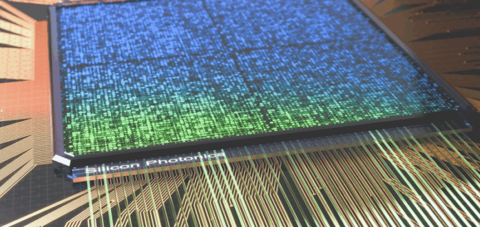
図34 3つの光対応データセンタープラットフォーム(LightningValley2、ThunderValley、Pegasus)と、Nexusラック内のAuroraテスト・計測プラットフォームで、ラック内およびラック間の接続が可能
図35 半導体パッケージング進化年表
図36 2.5D パッケージング構造図
図37 2.5D Si-Based Packaging Roadmap
図38 EMIBの実装(シリコンブリッジ)
図39 インターポーザーを備えた2.5DパッケージのFPGA + HBM
図40 RDL作製プロセスフロー
図41 パネルレベルのファンアウトプロセス
図42 ウェーハレベルのファンアウトプロセス
図43 ガラスコアインターポーザの構造
図44 ガラスインターポーザ製造プロセスフロー
図45 (a) 2.5Dアドバンストパッケージで構成されるスイッチ。5D アドバンストパッケージング、(b) TMV ベース、(c) TSV ベース、(d) TGV ベースのアドバンストパッケージングアーキテクチャ
図46 ASE ファンアウト CPO ソリューション
図47 ASE FOPOP プロセスフロー
図48 SPIL'CPOにおけるPIC/EIC統合のためのFOEB(Fan-Out Embedded Bridge)構造
図49 FOEB統合プロセスフロー
図50 TSMC光エンジンロードマップ
図51 TSMC iOISアーキテクチャ
図52 (a) EICとPICボンディングのためのTSMC-SoIC対面(F "F)技術。(b) COUPE の重要コンポーネントは、TSMC-SoIC ボンド、TDC、組み込みマイクロレンズ、メタルリフレクタで構成される
図53 ボンドピッチのスケーリングロードマップ
図54 スケールアップ光 I/O 技術ロードマップ

Summary
The global co-packaged optics (CPO) market stands at an inflection point, poised to fundamentally transform data center interconnect architecture over the coming decade. Driven primarily by the explosive growth of artificial intelligence workloads, particularly large language models and generative AI, CPO technology addresses critical bottlenecks in bandwidth, power consumption, and latency that conventional pluggable optical modules can no longer overcome.
Co-packaged optics integrates optical transceivers directly with switch ASICs or processors within the same package, dramatically shortening the electrical path between computing silicon and optical conversion. This architectural shift reduces power consumption from approximately 15 picojoules per bit with pluggable modules to around 5 picojoules per bit, with a projected path to below 1 picojoule per bit. The technology also enables significantly higher bandwidth density at the package edge, essential for next-generation switches operating at 51.2 terabits per second and beyond.
The market divides into two primary application segments: scale-out and scale-up networks. Scale-out applications encompass traditional data center switching fabrics using Ethernet or InfiniBand protocols, connecting racks and clusters across the facility. Scale-up applications target GPU-to-GPU and accelerator interconnects within AI training clusters, replacing copper-based solutions like NVIDIA's NVLink with optical alternatives that offer superior reach, bandwidth, and power efficiency. Initial CPO deployments are expected to target scale-up AI networks before expanding to broader scale-out infrastructure.
NVIDIA's announcement of Spectrum-X and Quantum-X silicon photonics switches at GTC 2025 marked a watershed moment for the industry, signaling that the dominant AI infrastructure provider is fully committed to CPO technology. These switches leverage TSMC's System on Integrated Chips (SoIC) technology with 3D hybrid bonding to achieve unprecedented integration density. Broadcom, the leading switch ASIC supplier, has pursued a complementary strategy with its Bailly CPO platform, emphasizing an open ecosystem approach that works with multiple packaging and photonics partners.
The CPO supply chain represents one of the semiconductor industry's most complex ecosystems, spanning photonic integrated circuit design, laser sources, electronic interface circuits, advanced packaging, optical alignment, and system integration. TSMC has emerged as a central player, providing both leading-edge logic processes and advanced packaging platforms including CoWoS and COUPE that enable tight integration of photonic and electronic chiplets. Critical bottlenecks remain in optical assembly and testing, where sub-micron alignment tolerances and specialized equipment create manufacturing challenges that the industry is actively working to resolve.
Key technology decisions facing the industry include the choice between 2.5D and 3D integration approaches, external versus integrated laser sources, and edge coupling versus grating coupling for fiber attachment. Most leading implementations have converged on external laser source architectures that keep temperature-sensitive lasers separate from heat-generating ASICs, improving reliability and enabling redundancy. Hybrid bonding technology is increasingly favored for achieving the interconnect density required for next-generation optical engines.
Hyperscale cloud providers including AWS, Microsoft Azure, Google, and Meta represent the primary demand drivers, with their massive AI infrastructure investments creating urgent requirements for CPO solutions. These companies collectively invest tens of billions of dollars annually in data center infrastructure and are actively evaluating or developing CPO technology for deployment beginning in 2026-2027.
The competitive landscape features established semiconductor giants alongside well-funded startups. Companies like Ayar Labs, Lightmatter, and Celestial AI are pioneering novel architectures including 3D photonic interposers and photonic fabric technologies that may reshape the market. Meanwhile, traditional optical component suppliers including Lumentum, Coherent, and Marvell are adapting their portfolios for CPO applications. As AI model sizes continue growing exponentially and data center power constraints tighten, CPO technology offers a compelling solution to interconnect challenges that will only intensify. The technology's ability to deliver higher bandwidth at lower power positions it as essential infrastructure for the AI era.
The Global Co-Packaged Optics Market 2026-2036 delivers comprehensive analysis of the rapidly emerging CPO industry, examining how this transformative technology is reshaping data centre interconnect architecture to meet the unprecedented bandwidth demands of artificial intelligence and machine learning workloads. As hyperscale operators and AI infrastructure providers confront critical limitations in power consumption, latency, and bandwidth density with conventional pluggable optical modules, co-packaged optics has emerged as the definitive next-generation solution, integrating optical transceivers directly with switch ASICs and accelerators to achieve dramatic improvements in performance and efficiency.
This authoritative report provides semiconductor industry professionals, investors, data centre operators, and technology strategists with detailed market forecasts projecting CPO growth from nascent commercial deployments through mass adoption, with granular segmentation by application (scale-out networking and scale-up AI interconnects), integration technology (2D, 2.5D, and 3D packaging), and end-use sector. The research examines the complete CPO value chain, from photonic integrated circuit design and laser sources through advanced semiconductor packaging and system integration, identifying critical bottlenecks, emerging solutions, and strategic opportunities across each segment.
Drawing on extensive primary research including interviews with industry leaders across the CPO ecosystem, the report delivers actionable intelligence on technology roadmaps from dominant players including NVIDIA and Broadcom, evaluates competing packaging approaches from leading OSATs and foundries, and assesses the readiness of hyperscale customers to deploy CPO at scale. Detailed company profiles provide strategic analysis of 55 organisations actively shaping the CPO landscape, while comprehensive benchmarking enables direct comparison of competing technologies, products, and ecosystem strategies.
Report contents include
Companies Profiled include Alphawave Semi, AMD, Amkor Technology, ASE Holdings, Astera Labs, Avicena, AXT, Ayar Labs, Broadcom, CEA-Leti, Celestial AI, Cisco, Coherent, Corning, Credo, DenseLight, EFFECT Photonics, EVG, Fabrinet, FOCI (Fiber Optical Communication Inc.), FormFactor, Foxconn, GlobalFoundries, Henkel, Hewlett Packard Enterprise, imec, Intel, JCET Group, Lightmatter, LioniX International, Lumentum, MACOM, Marvell, MediaTek, Molex, Nubis Communications, NVIDIA, OpenLight, Ranovus, Rockley Photonics, Samtec, Scintil Photonics and more.
Key Questions Answered
What is the total addressable market for co-packaged optics through 2036?
How will CPO adoption differ between scale-out networking and scale-up AI applications?
Which advanced packaging technologies offer the best performance-cost trade-offs for CPO?
How are NVIDIA and Broadcom positioning their CPO strategies differently?
What role will TSMC's COUPE and iOIS platforms play in CPO manufacturing?
Which laser integration approach will achieve commercial dominance?
How will optical alignment and fiber attachment challenges be resolved at scale?
When will hyperscale data centres begin volume CPO deployment?
What are the key investment opportunities across the CPO value chain?
How does CPO compare to high-density connector alternatives being developed?
Who Should Purchase This Report
Semiconductor company executives evaluating CPO market entry or expansion
Photonics and optical component manufacturers assessing strategic positioning
Advanced packaging service providers planning CPO capability development
Data centre operators and hyperscale infrastructure planners
AI chip and accelerator designers exploring optical interconnect integration
Venture capital and private equity investors targeting CPO opportunities
Investment analysts covering semiconductor, photonics, and data centre sectors
Strategic planners at system OEMs and ODMs
Supply chain managers responsible for optical and packaging sourcing
Technology policy makers assessing semiconductor industry trends
Table of Contents1 EXECUTIVE SUMMARY
1.1 Report Overview and Key Findings
1.2 Market Definition and Scope
1.2.1 Definition of Co-Packaged Optics (CPO)
1.2.2 Scope of This Report
1.3 Key Market Drivers and Restraints
1.4 Modern High-Performance AI Data Centre Architecture
1.4.1 Physical Infrastructure Hierarchy
1.4.2 Network Architecture
1.4.3 Power and Cooling Considerations
1.5 Switches: Key Components in Modern Data Centres
1.5.1 Switch Architecture Evolution
1.5.2 Switch ASIC Technology
1.5.3 Optical Transceiver Requirements
1.6 Advancements in Switch IC Bandwidth and the Need for CPO Technology
1.6.1 Historical Bandwidth Scaling
1.6.2 SerDes Technology Evolution
1.6.3 Electrical Signalling Limits
1.6.4 Front-Panel Density Constraints
1.6.5 Power Consumption Trajectory
1.7 Overview of Key Challenges in Data Centre Architectures
1.7.1 Thermal Management
1.7.2 Power Delivery
1.7.3 Cable Management
1.7.4 Reliability and Serviceability
1.7.5 Standards and Interoperability
1.8 Key Trend of Optical Transceivers in High-End Data Centres
1.8.1 Historical Evolution
1.8.2 Technology Migration Path
1.9 Design Decisions: CPO vs. Pluggables Comparison
1.9.1 Performance Comparison
1.9.2 Operational Comparison
1.9.3 Economic Comparison
1.10 What is an Optical Engine (OE)?
1.10.1 Functional Description
1.10.2 Optical Engine Components
1.10.3 Performance Parameters
1.11 Heterogeneous Integration and Co-Packaged Optics
1.11.1 The Heterogeneous Integration Imperative
1.11.2 Integration Approaches for CPO
1.11.3 TSMC's Role in Heterogeneous Integration
1.15 Overview of Interconnection Techniques in Semiconductor Packaging
1.15.1 Wire Bonding
1.15.2 Flip-Chip Bumping
1.15.3 Micro-Bumping
1.15.4 Through-Silicon Via (TSV)
1.15.5 Hybrid Bonding
1.15.6 Redistribution Layer (RDL)
1.16 Key CPO Applications: Network Switch and Computing Optical I/O
1.16.1 Scale-Out Network Switching
1.16.2 Scale-Up Computing Optical I/O
1.17 EIC/PIC Integration by Advanced Interconnect Techniques
1.17.1 Integration Requirements
1.18 2D to 3D EIC/PIC Integration Options
1.18.1 2D Integration Architecture
1.18.2 2.5D Integration Architecture
1.18.3 3D Integration Architecture
1.19 Benchmark of Different Packaging Technologies for EIC/PIC
1.20 Examples of Packaging a 3D Optical Engine with an IC
1.20.1 Configuration 1: EIC-on-PIC with Micro-Bumps
1.20.2 Configuration 2: PIC-on-EIC with Through-Silicon Vias
1.20.3 Configuration 3: 3D SoIC with Hybrid Bonding
1.21 Types of CPO + XPU/Switch ASIC Packaging Structures
1.21.1 Type I: Optical Engines on Package Periphery
1.21.2 Type II: Optical Engines Co-Located with ASIC on Interposer
1.21.3 Type III: 3D Stacked Optical Engines
1.22 Challenges and Future Potential of CPO Technology
1.22.1 Technical Challenges
1.22.2 Commercial Challenges
1.22.2.1 Future Potential
1.23 NVIDIA vs. Broadcom: Strategic Comparison in AI Infrastructure and CPO
1.23.1 NVIDIA's CPO Strategy: Vertical Integration
1.23.2 Broadcom's CPO Strategy: Open Ecosystem
1.23.3 Competitive Dynamics
1.23.4 CPO Product Benchmark: NVIDIA vs. Broadcom
1.23.5 NVIDIA and Broadcom: Divergent CPO Ecosystems
1.24 Current AI System Architecture
1.24.1 NVIDIA DGX/HGX Architecture
1.25 Future AI Architecture
1.26 Market Forecast
1.26.1 Server Boards, CPUs, and GPUs/Accelerators
1.26.2 Optical I/O for AI Interconnect CPO Forecast (Units Shipped)
1.26.3 Optical I/O for AI Interconnect CPO Forecast (Revenue/Market Size)
1.26.4 CPO Network Switches for AI Accelerators Forecast (Units Shipped)
1.26.5 CPO Network Switches for AI Accelerators Forecast (Market Size and Revenue)
1.26.6 Total CPO Market Overview
1.26.7 Total CPO by Different EIC/PIC Integration Technology (Unit Shipments)
1.26.8 System Integration of Network Switches by Packaging Technologies
1.26.9 System Integration of Optical I/O Forecast by Packaging Technologies
1.27 Co-packaged optics (CPO) industrial ecosystem
1.27.1 PIC Design Segment
1.27.2 ASIC and xPU Design Segment
1.27.3 Laser Sources Segment
1.27.4 SOI Wafer and Epi-Wafer Segment
1.27.5 EIC, Retimers, SerDes, and PHY Segment
1.27.6 Connectors and Fibers Segment
1.27.7 Foundries Segment
1.27.8 Packaging, Assembling, and Testing Segment
1.27.9 System and Equipment Segment
1.27.10 End Customers (Hyperscalers) Segment
1.27.11 Ecosystem Interdependencies and Strategic Implications
2 CHALLENGES AND SOLUTIONS FOR FUTURE AI SYSTEMS
2.1 The Rise and Challenges of Large Language Models (LLMs)
2.1.1 The Explosive Growth of AI and Generative AI
2.1.1.1 Historical Context and Acceleration
2.1.1.2 Compute Demand Scaling
2.1.1.3 Generative AI Market Expansion
2.1.2 Modern High-Performance AI Data Centre Requirements
2.1.2.1 Compute Density Requirements
2.1.2.2 Network Topology Requirements
2.1.2.3 Availability and Reliability Requirements
2.1.3 NVIDIA's State-of-the-Art AI Systems
2.1.3.1 DGX H100 and HGX H100
2.1.4 Switches: Key Components in Modern Data Centres
2.1.4.1 Switch Hierarchy in AI Data Centres
2.2 Scale-Up, Scale-Out, and Scale-Across Networks
2.2.1 Scale-Up Networks: GPU-to-GPU Interconnects
2.2.1.1 NVIDIA NVLink Implementation
2.2.1.2 CPO Value Proposition for Scale-Up
2.2.2 Scale-Out Networks: Rack-to-Rack Communications
2.2.2.1 Ethernet-Based Scale-Out
2.2.2.2 InfiniBand for AI
2.2.2.3 CPO Value Proposition for Scale-Out
2.2.3 Scale-Up, Scale-Out, and Scale-Across Comparison
2.3 Challenges in Network Switch Interconnects for High-End Data Centres
2.3.1 Roadmap of Interconnect Technology for Network Switches in High-End Data Centres
2.3.1.1 Technology Generations
2.3.2 SerDes Bottleneck in High-Bandwidth Systems
2.3.2.1 SerDes Function
2.3.2.2 Channel Loss Challenges
2.3.3 Solutions to SerDes Bottlenecks in High-Bandwidth Systems
2.3.3.1 Linear-Drive Electronics
2.3.3.2 Near-Package Optics
2.3.3.3 Co-Packaged Optics
2.3.4 Pluggable Optics: Current Bottlenecks and Limitations
2.3.4.1 Form Factor Constraints
2.3.4.2 Electrical Interface Limitations
2.3.4.3 Thermal Management Challenges
2.3.4.4 Serviceability Trade-offs
2.3.5 On-Board Optics (OBO)
2.3.6 Co-Packaged Optics (CPO)
2.3.6.1 CPO Architecture
2.3.6.2 Key Enabling Technologies
2.3.6.3 Performance Benefits
2.3.6.4 Implementation Challenges
2.3.7 Transmission Losses in Pluggable Optical Transceiver Connections
2.3.7.1 Total Path Loss
2.3.8 Pluggable Optics vs. CPO
2.3.9 Design Decisions for CPO Compared to Pluggables
2.3.10 Advancements in Switch IC Bandwidth and the Need for CPO Technology
2.3.10.1 Bandwidth Scaling Trajectory
2.3.10.2 Physical Constraints at Scale
2.3.11 L2 Frontside Network Architecture Diagram: CPO vs. Non-CPO
2.4 Challenges in Compute Switch Interconnects (Optical I/O) for High-End Data Centres
2.4.1 Number of Copper Wires in Current AI System Interconnects
2.4.1.1 NVLink Copper Cable Count
2.4.1.2 SuperPOD Cable Complexity
2.4.2 Limitations of Current Copper Systems in AI
2.4.3 NVIDIA's Connectivity Choices: Copper vs. Optical for High-Bandwidth Systems
2.4.3.1 Current Generation: Copper-Centric
2.4.3.2 Transition Generation: Hybrid Approach
2.4.3.3 Future Generation: Optical-First
2.4.3.4 Strategic Implications
2.4.4 Copper vs. Optical for High-Bandwidth Systems: Benchmark
2.4.5 Migration from Copper to Optical Interconnects for High-End AI Systems
2.4.6 Current AI System Architecture
2.4.7 L1 Backside Compute Architecture with Copper Systems
2.4.8 L1 Backside Compute Architecture with Optical Interconnect: Co-Packaged Optics (CPO)
2.4.9 Opportunities for Swapping Copper to Optical
2.5 Future AI Systems in High-End Data Centres
2.5.1 Power Efficiency Comparison: CPO vs. Pluggable Optics vs. Copper Interconnects
2.5.1.1 Power Consumption Breakdown
2.5.2 Latency of 60cm Data Transmission Technology Benchmark
2.5.3 Future AI Architecture (Short to Mid-Term)
2.5.4 Future AI Architecture (Long-Term)
3 INTRODUCTION TO CO-PACKAGED OPTICS (CPO)
3.1 Photonic Integrated Circuits (PICs) Key Concepts
3.1.1 What are Photonic Integrated Circuits (PICs)?
3.1.1.1 Fundamental Definition
3.1.1.2 Material Platforms
3.1.1.3 Integration Levels
3.1.2 PICs vs. Silicon Photonics: What are the Differences?
3.1.2.1 Silicon Photonics: A Specific Implementation
3.1.2.2 Why Silicon Photonics Dominates CPO
3.1.3 PIC Architecture
3.1.3.1 Transmit Path Architecture
3.1.3.2 Receive Path Architecture
3.1.3.3 Supporting Functions
3.1.4 Advantages and Challenges of PICs
3.2 Optical Engine (OE)
3.2.1 What is an Optical Engine?
3.2.1.1 Optical Engine Composition
3.2.1.2 Optical Engine vs. Pluggable Transceiver
3.2.2 How an Optical Engine Works
3.2.2.1 Transmit Path Operation
3.2.2.2 Receive Path Operation
3.2.2.3 Critical Performance Parameters
3.2.3 Optical Power Supplies
3.2.3.1 Why External Laser Sources?
3.2.3.2 External Laser Source Architectures
3.2.3.3 Optical Power Delivery
3.3 Co-Packaged Optics
3.3.1 Three Key Concepts in Co-Packaged Optics (CPO)
3.3.1.1 Concept 1: Proximity Integration
3.3.1.2 Concept 2: Functional Partitioning
3.3.1.3 Concept 3: Coherent Ecosystem Development
3.3.2 Key Technology Building Blocks for CPO
3.3.2.1 Silicon Photonics PIC
3.3.2.2 Electronic IC (EIC)
3.3.2.3 EIC-PIC Integration
3.3.2.4 Fibre Array Units (FAUs)
3.3.2.5 External Laser Source
3.3.2.6 Advanced Packaging Platform
3.3.3 Benefits of CPO: Latency Reduction
3.3.3.1 Sources of Latency in Optical Interconnects
3.3.3.2 CPO Latency Advantages
3.3.4 Benefits of CPO: Power Consumption Reduction
3.3.4.1 Power Consumption Breakdown
3.3.4.2 Why CPO Consumes Less Power
3.3.5 Benefits of CPO: Data Rate Improvements
3.3.5.1 Pluggable Scaling Limitations
3.3.5.2 CPO Scaling Advantages
3.3.5.3 Data Rate Scaling Roadmap
3.3.6 Overview of Value Proposition of CPO
3.3.6.1 Value for Hyperscale Data Centre Operators
3.3.6.2 Value for Network Equipment Vendors
3.3.6.3 Value for the Technology Ecosystem
3.3.7 Future Challenges in CPO
3.3.7.1 Manufacturing and Yield Challenges
3.3.7.2 Thermal Management Challenges
3.3.7.3 Serviceability and Reliability Challenges
3.3.7.4 Ecosystem and Standardisation Challenges
3.3.7.5 Cost Challenges
3.4 CPO Standards
3.4.1 OIF Co-Packaging Framework
3.4.2 OIF Standards for 1.6T and 3.2T CPO Module
3.4.3 External Laser Small Form Pluggable (ELSFP) Implementation Agreement
3.4.4 Telemetry and Management
3.4.5 OIF's CEI-112G XSR / XSR+ PAM4
3.4.6 UCIe Standard and Its Relationship to CPO
3.4.7 The CPO Standards Process in China
4 PACKAGING FOR CO-PACKAGED OPTICS (CPO)
4.1 Introduction to CPO Packaging
4.1.1 Key Components to be Packaged in an Optical Transceiver
4.1.1.1 Photonic Integrated Circuit (PIC)
4.1.1.2 Electronic Integrated Circuit (EIC)
4.1.1.3 Laser Source Interface
4.1.1.4 Fibre Array Unit (FAU)
4.1.1.5 Host ASIC Interface
4.1.2 Heterogeneous Integration and Co-Packaged Photonics
4.1.2.1 Why Heterogeneous Integration for CPO?
4.1.2.2 Heterogeneous Integration Approaches for CPO
4.1.2.3 Integration Hierarchy for CPO
4.1.3 CPO for Network Switch: Packaging Concept
4.1.3.1 Switch Architecture with CPO
4.1.3.2 Package Configuration Options
4.1.3.3 Packaging Requirements for Switch CPO
4.1.4 1.6 Tbps Co-Packaged Optics for Network Switch
4.1.4.1 Integration Approach
4.1.5 CPO as Optical I/O for XPUs: Packaging Concept
4.1.5.1 The Scale-Up Interconnect Challenge
4.1.5.2 XPU-CPO Packaging Concept
4.1.5.3 Implementation Approaches
4.1.5.4 NVIDIA's Approach to XPU Optical I/O
4.1.5.5 Packaging Implications for XPU Optical I/O
4.1.5.6 System Architecture Evolution
4.1.6 CPO Integration for Compute Silicon
4.1.6.1 System Configuration
4.1.6.2 Integration Architecture
4.1.6.3 Thermal Partitioning
4.1.6.4 Enabled Architectures
4.1.7 Overview of CPO Packaging Technologies
4.2 Overview and Development Roadmap of 2.5D and 3D Advanced Semiconductor Packaging Technologies
4.2.1 Evolution Roadmap of Semiconductor Packaging
4.2.2 Semiconductor Packaging Overview
4.2.3 Key Metrics for Advanced Semiconductor Packaging Performance
4.2.4 Overview of Interconnection Techniques in Semiconductor Packaging
4.2.5 Overview of 2.5D Packaging Structure
4.2.6 2.5D Package Components
4.2.7 Benefits for CPO
4.2.8 Challenges for CPO
4.3 2.5D Silicon-Based Packaging Technologies
4.3.1 2.5D Packaging Involving Silicon as Interconnect
4.3.2 Silicon Interposer Technology
4.3.3 Silicon Bridge Technology
4.3.4 CPO Implications
4.3.5 Through-Silicon Via (TSV): Current State and Future
4.3.5.1 TSV Fabrication Process
4.3.5.2 TSV Technology Generations
4.3.5.3 TSV Challenges for CPO
4.3.5.4 Future TSV Development
4.3.6 Development Trends for 2.5D Silicon-Based Packaging
4.3.6.1 Interposer Size Scaling
4.3.6.2 Routing Density Advancement
4.3.6.3 Cost Reduction Initiatives
4.3.6.4 Integration with Advanced Features
4.3.7 Silicon Interposer vs. Silicon Bridge Benchmark
4.3.7.1 Implications for CPO
4.4 2.5D Organic-Based Packaging Technologies
4.4.1 2.5D Packaging: High-Density Fan-Out (FO) Packaging
4.4.1.1 Fan-Out Technology Concept
4.4.1.2 High-Density Fan-Out Variants
4.4.1.3 Advantages for CPO
4.4.1.4 Challenges for CPO
4.4.2 Redistribution Layer (RDL)
4.4.2.1 RDL Fabrication Process
4.4.2.2 RDL Design Considerations for CPO
4.4.3 Electronic Interconnects: SiO2 vs. Organic Dielectric
4.4.4 Panel Level Fab-Out
4.4.4.1 Panel-Level Processing
4.4.4.2 Advantages for CPO
4.4.4.3 Challenges for CPO
4.4.5 Wafer Level Fan-Out
4.4.5.1 Wafer-Level Processing
4.4.5.2 Advantages for WLFO
4.4.5.3 Challenges for WLFO
4.4.6 Wafer-Level Fan-Out vs. Panel-Level Fan-Out
4.4.6.1 Selection Criteria for CPO
4.4.7 Key Trends in Fan-Out Packaging
4.4.8 Challenges in Future Fan-Out Processes
4.4.8.1 Die Shift and Placement Accuracy
4.4.8.2 Warpage Control
4.4.8.3 Yield and Cost
4.4.8.4 High-Frequency Performance
4.5 2.5D Glass-Based Packaging Technologies
4.5.1 Roles of Glass in Semiconductor Packaging
4.5.1.1 Glass Properties Relevant to Packaging
4.5.1.2 Applications in Packaging
4.5.1.3 Glass Core as Interposer for Advanced Semiconductor Packaging
4.5.2 Overcoming Limitations of Silicon Interposers with Glass
4.5.2.1 Size Limitation
4.5.2.2 Optical Opacity
4.5.2.3 Dielectric Loss
4.5.2.4 Cost Structure
4.5.2.5 Remaining Silicon Advantages
4.5.3 Glass vs. Molding Compound
4.5.3.1 Implications for CPO
4.5.4 Glass Core (Interposer) Package: Process Flow
4.5.5 Challenges of Glass Packaging
4.5.5.1 Handling and Breakage
4.5.5.2 Via Formation and Metallisation
4.5.5.3 Thermal Conductivity
4.5.5.4 RDL Adhesion
4.5.5.5 Warpage Control
4.6 3D Advanced Semiconductor Packaging Technologies
4.6.1 Evolution of Bumping Technologies
4.6.1.1 Solder Bumps (C4)
4.6.1.2 Copper Pillar Bumps
4.6.1.3 Micro-Bumps
4.6.1.4 Hybrid Bonding (Bumpless)
4.6.2 Challenges in Scaling Bumps
4.6.2.1 Mechanical Challenges
4.6.2.2 Electrical Challenges
4.6.2.3 Manufacturing Challenges
4.6.2.4 Implications for CPO
4.6.3 Micro-Bump for Advanced Semiconductor Packaging
4.6.3.1 Micro-Bump Structure
4.6.4 Bumpless Cu-Cu Hybrid Bonding
4.6.4.1 Hybrid Bonding Concept
4.6.4.2 Process Fundamentals
4.6.4.3 Key Characteristics
4.6.4.4 Benefits for CPO
4.6.5 Three Ways of Cu-Cu Hybrid Bonding: Benchmark
4.6.5.1 Die-to-Die (D2D)
4.6.5.2 Die-to-Wafer (D2W)
4.6.5.3 Wafer-to-Wafer (W2W)
4.6.6 Challenges in Cu-Cu Hybrid Bonding Manufacturing Process
4.7 CPO Packaging: EIC and PIC Integration
4.7.1 EIC/PIC Integration by Conventional Interconnect Techniques
4.7.1.1 Wire Bond Integration
4.7.1.2 Flip-Chip Integration (2D)
4.7.2 EIC/PIC Integration by Emerging Interconnect Techniques
4.7.2.1 2.5D Interposer Integration
4.7.2.2 3D Micro-Bump Stacking
4.7.2.3 3D Hybrid Bonding
4.7.3 2D to 3D EIC/PIC Integration Options
4.7.3.1 Technology Transition Drivers
4.7.3.2 2D to 3D Integration Evolution
4.7.4 Integration Roadmap by CPO Segment
4.7.5 Benchmarking of Different Packaging Technologies for EIC/PIC
4.7.6 Pros and Cons of 2D Integration of EIC/PIC
4.7.7 Pros and Cons of 2.5D Integration of EIC/PIC
4.7.8 Pros and Cons of 3D Hybrid Integration of EIC/PIC
4.7.9 Pros and Cons of 3D Monolithic Integration of EIC/PIC
4.8 TSV for EIC/PIC Integration
4.8.1 TSV for EIC/PIC Integration in CPO
4.8.1.1 TSV Configurations for EIC/PIC
4.8.1.2 Design Considerations
4.8.2 Benefits of TSV for PIC/EIC Integration
4.8.3 Cisco Packaging Architectures of Optical Engine Over Generations
4.8.4 Cisco: 2.5D Chip-on-Chip (CoC) Packaging Architecture for EIC/PIC Integration
4.8.4.1 Architecture Description
4.8.4.2 Manufacturing Considerations
4.8.5 Cisco: 3D TSV for PIC/EIC Integration
4.8.5.1 Architecture Description
4.8.5.2 Benefits of TSV Integration
4.8.5.3 Manufacturing Considerations
4.8.6 Key TSV Fabrication Steps and Challenges in CPO
4.8.6.1 Fabrication Process Flow
4.8.7 Packaging Options for Silicon Photonics
4.8.8 Pros and Cons of 2.5D Si Interposer for EIC/PIC Integration
4.9 Fan-Out for EIC/PIC Integration
4.9.1 ASE's Proposed Fan-Out Solution for CPO Packaging
4.9.1.1 ASE Fan-Out CPO Concept
4.9.2 FOPOP from ASE: Process
4.9.3 Analysis of FOPOP vs. Wire Bond Packaging for CPO
4.9.4 Optical Packaging Process Considerations for Silicon Photonics - ASE
4.9.5 SPIL's Fan-Out Embedded Bridge (FOEB) Structure for PIC/EIC Integration in CPO
4.9.6 Process Flow of Integrating PIC and EIC in a FOEB Structure
4.9.7 Process Challenges in Packaging Optical Engines
4.9.8 Challenges of Using Fan-Out for EIC/PIC Integration
4.10 Glass-Based CPO Packaging Technologies
4.10.1 Glass-Based Co-Packaged Optics
4.10.1.1 Corning's Glass CPO Vision
4.10.2 Glass CPO Package Architecture
4.10.3 Glass-Based CPO Process Development
4.10.3.1 Corning's 102.4 Tb/s Test Vehicle Demonstration
4.11 Hybrid Bonding for EIC/PIC Integration
4.11.1 TSMC: Integrated HPC Technology Platform for AI
4.11.2 iOIS: Integrated Optical Interconnection System from TSMC
4.11.3 Combining EIC and PIC with 3D SoIC Bond
4.11.4 Roadmap of Bond Pitch Scaling
4.12 System Integration of Optical Engine and ASIC/XPU
4.12.1 Co-Packaging vs. Co-Packaged Optics (CPO)
4.12.2 Three Types of CPO + XPU/Switch ASIC Packaging Structures
4.12.2.1 Type 1: 2D/2.5D Peripheral Integration
4.12.2.2 Type 2: 2.5D with Embedded Bridge
4.12.2.3 Type 3: 3D Stacked Integration
4.13 Future 3D-CPO Structure
4.13.1 Future 3D-CPO Architecture Vision
4.13.2 NVIDIA's 3D Integration of SoC, HBM, EIC, and PIC on Co-Packaged Substrates
4.13.2.1.1 Architecture Overview
4.13.2.1.2 Integration Approach
4.13.2.1.3 Key Innovations
4.14 Optical Alignment and Laser Integration
4.14.1 How CPO is Built and the Bottleneck
4.14.2 The fibre attach bottleneck
4.14.3 Interface Between Coupler and FAU
4.14.4 Grating vs. Edge Couplers: Challenges in High-Density Optical I/O for Silicon Photonics
4.14.5 Challenges in High-Density Optical I/O for Silicon Photonics
4.15 Fiber Array Unit (FAU)
4.15.1 Optical Alignment Challenges and Solutions
4.15.2 Two Alignment Approaches
4.15.3 Reducing Optical Fiber Packaging Complexity
4.15.4 Key Technical Challenges
4.15.4.1 The Size Mismatch Between Silicon Waveguides and Planar Optical Fibers
4.15.5 Fiber Attach Methods
4.15.6 Key Players in FAU for CPO
4.15.7 Benchmark of Optical Fiber Alignment Structure Variations
4.15.8 Suppliers of Other Optical Components in CPO
4.16 Suppliers of Other Optical Components in CPO
4.17 Laser Integration
4.17.1 On-Chip Light Source Integration Methods
4.17.2 External Lasers for CPO
4.17.3 Laser Attach Technology Benchmark
4.17.4 Benchmark of Different Laser Integration Technologies
5 CO-PACKAGED OPTICS MARKET ANALYSIS
5.1 CPO Market Definition and Scope
5.2 CPO Market Size and Growth Projections
5.3 Switch CPO Market Analysis
5.3.1 Market Overview and Drivers
5.3.2 Deployment Timeline and Adoption Phases
5.3.3 Volume Projections and Market Sizing
5.3.4 Market Concentration and Regional Distribution
5.3.5 Pricing Trajectory and Cost Dynamics
5.4 XPU Optical I/O Market Analysis
5.4.1 Market Drivers and Value Proposition
5.4.2 Adoption Timeline and Platform Evolution
5.4.3 Volume and Revenue Projections
5.4.4 Market Segmentation by Platform
5.4.5 Technology Requirements and Differentiation
5.5 CPO Pricing and Cost Analysis
5.5.1 Current Pricing Landscape
5.5.2 Cost Trajectory and Reduction Drivers
5.5.3 Cost Parity Timeline and Dynamics
5.5.4 Pricing Strategy Implications
5.6 Regional Market Dynamics
5.6.1 North America
5.6.2 Asia-Pacific
5.6.3 Europe
5.6.4 Rest of World
5.7 Total Addressable Market Analysis
5.7.1 Core TAM Segments
5.7.2 Serviceable Addressable Market (SAM)
5.8 Market Forecast by Component
5.9 Market Forecast by Technology Generation
5.9.1 Optical Engine Bandwidth Evolution
5.9.2 Generation Lifecycle Analysis
5.10 Market Restraints and Barriers
5.10.1 Manufacturing Yield and Cost
5.10.2 Serviceability and Field Replacement Concerns
5.10.3 Standards Maturity and Interoperability
5.10.4 Supply Chain Capacity Constraints
5.10.5 Competitive Alternatives
5.11 Adoption Curve Analysis
5.11.1 Technology Adoption Framework
5.11.1.1 Innovators (2024-2026)
5.11.1.2 Early Adopters (2026-2028)
5.11.1.3 Early Majority (2028-2031)
5.11.1.4 Late Majority (2031-2034)
5.11.1.5 Laggards (2034+)
5.11.2 Segment-Specific Adoption Curves
5.12 Adoption Accelerators and Inhibitors
5.12.1 Adoption Curve Implications
5.13 Competitive Landscape Evolution
5.13.1 Current Competitive Positioning
5.13.2 Integrated Device Manufacturers (IDMs)
5.13.3 Silicon Photonics Specialists
5.13.4 Foundry/OSAT Providers
5.13.5 System Vendors
5.13.6 Laser Suppliers
5.13.7 Competitive Dynamics and Market Structure Evolution
5.13.7.1 Near-Term Dynamics (2025-2028)
5.13.7.1.1 Expected Evolution (2028)
5.13.7.2 Mid-Term Dynamics (2028-2032)
5.13.7.2.1 Expected Evolution (2032)
5.13.7.3 Long-Term Dynamics (2032-2036)
5.13.7.3.1 Expected Evolution (2036)
5.13.8 Vertical Integration Trends
5.13.8.1 Integration Strategy Framework
5.13.8.1.1 Full Vertical Integration (Broadcom, Intel Model)
5.13.8.1.2 Partial Integration (Cisco, NVIDIA Model)
5.13.8.1.3 Fabless/Assembly-Light (Ayar Labs, Ranovus Model)
5.13.8.1.4 Platform Provider (TSMC Model)
5.13.8.2 Strategic Implications of Integration Trends
5.14 Scenario Analysis
5.14.1 Scenario Framework
5.14.2 Scenario Definitions
5.14.3 Bull Case Scenario
5.14.4 Base Case Scenario
5.14.5 Bear Case Scenario
5.14.6 Scenario Comparison and Key Variables
6 GLOBAL MARKET TRENDS IN DATACOM
6.1 Introduction to DATACOM Market Dynamics
6.1.1 Overview of the Data Communications Market
6.1.1.1 Market Definition and Scope
6.1.1.2 Market Size and Growth
6.1.2 Key Market Drivers
6.1.2.1 Artificial Intelligence and Machine Learning
6.1.2.2 Cloud Computing Growth
6.1.2.3 Data Growth
6.1.2.4 Power and Sustainability Pressures
6.2 Application Trends
6.2.1 AI and Machine Learning Workload Growth
6.2.1.1 The AI Training Revolution
6.2.1.2 Training Cluster Architecture Evolution
6.2.1.3 AI Inference Deployment
6.2.1.4 Market Quantification
6.2.1.5 Implications for CPO
6.2.2 Hyperscale Data Centre Expansion
6.2.2.1 Defining Hyperscale
6.2.3 Global Hyperscale Capacity
6.2.4 Regional Distribution
6.2.5 Hyperscaler Investment Trends
6.2.5.1 Capital expenditure acceleration
6.2.5.2 AI-Specific Infrastructure
6.2.5.3 Implications for CPO
6.2.6 Edge Computing and Distributed AI
6.2.6.1 Market Growth
6.2.7 Edge AI Applications
6.2.8 Edge Network Architecture
6.3 Technology Trends
6.3.1 Technology Trends Overview
6.3.1.1 Key Technology Vectors
6.3.1.2 Technology Interdependencies
6.3.2 Technology Trends: Packaging
6.3.3 Universal Chiplet Interconnect Express (UCIe)
6.3.4 Laser Sources for CPO
6.3.5 External vs. Integrated Laser
7 MARKET OUTLOOK
7.1 Scale-Out Outlook
7.1.1 Scale-Out CPO Market Evolution
7.1.1.1 Scale-Out Market Drivers
7.1.1.2 Market Evolution Phases
7.1.1.3 Scale-Out CPO Market Forecast
7.1.2 Scale-Out Technology Roadmap
7.1.2.1 Technology Generation Evolution
7.1.2.2 Technology Enablers by Generation
7.1.3 Scale-Out Key Players and Competitive Landscape
7.2 Scale-Up Outlook
7.2.1 Scale-Up CPO Market Evolution
7.2.2 Copper to Optical Transition
7.2.3 Optical I/O Solution
7.2.4 Scale-Up CPO Market Forecast
7.2.5 Market Evolution Phases
7.2.6 Scale-Up Technology Roadmap
7.2.6.1 NVIDIA Optical I/O Evolution
7.2.6.2 AMD Optical I/O Evolution
7.2.6.3 Custom Silicon Optical I/O
7.2.7 Scale-Up Key Players and Competitive Landscape
7.2.7.1 Competitive Landscape Overview
7.3 High-Density Connectors
7.3.1 High-Density Connectors vs. CPO
7.3.1.1 Scenario 1: Connectors Enable Extended Pluggable (Low CPO Impact)
7.3.1.2 Scenario 2: Connectors Complement CPO (Moderate Impact)
7.3.1.3 Scenario 3: Connectors Enable "Near-Packaged" Optics (Moderate CPO Impact)
7.3.1.4 Scenario 4: Connector Development Delays (Positive CPO Impact)
7.4 Emerging Supply Chain Dynamics
7.4.1 Geographic Concentration in CPO Supply Chains
7.5 Third-Party Suppliers and Systems Integrators
7.5.1 Multi-Tier Supply Chain Architecture
7.5.1.1 Tier 1: Silicon Photonics Platform
7.5.1.2 Tier 2: CPO Assembly (OSAT)
7.5.1.3 Tier 3: Fiber Array Unit (FAU) Suppliers
7.5.1.4 Tier 4: External Laser Source (ELS) Suppliers
7.5.1.5 Tier 5: Optical Fiber Supply
7.5.1.6 Tier 6: Optical Sub-Assembly Integration
7.5.2 Strategic Implications for Supply Chain Participants
8 COMPANY PROFILES (61 company profiles)9 APPENDIX
9.1 Research Methodology and Data Sources
10 REFERENCESList of Tables/Graphs表の一覧
表1 CPO Market Drivers and Restraints Analysis
表2 Key Data Centre Architecture Challenges Summary
表3 Key Data Centre Architecture Challenges Summary
表4 Form Factor Evolution and Density Comparison
表5 Optical Transceiver Power Consumption by Generation
表6 Technology Migration Decision Framework
表7 CPO vs. Pluggables Decision Matrix
表8 Semiconductor Packaging Interconnection Techniques Overview
表9 CPO Application Segmentation (Scale-Out vs. Scale-Up)
表10 EIC/PIC Integration Methods Comparison
表11 Integration Technology Selection Criteria
表12 Detailed Technical Comparison: 2D vs 2.5D vs 3D
表13 3D Integration Sub-Categories Comparison
表14 Packaging Technology Benchmark for EIC/PIC Integration
表15 CPO Technology Challenges and Mitigation Strategies
表16 NVIDIA vs. Broadcom Strategic Positioning Comparison
表17 NVIDIA vs. Broadcom CPO Product Specifications Benchmark
表18 Server Boards, CPUs, and GPU/Accelerator Forecast (2026-2036)
表19 Optical I/O CPO Unit Shipment Forecast (2026-2036)
表20 Optical I/O CPO Revenue Forecast (2026-2036)
表21 CPO Network Switch Unit Shipment Forecast
表22 CPO Network Switch Revenue Forecast (2026-2036)
表23 Total CPO Market Size and Revenue (2026-2036)
表24 CPO Unit Shipments by Integration Technology
表25 Network Switch CPO Adoption by Packaging Technology
表26 Optical I/O Forecast by Packaging Technology
表27 PIC Design Segment - Key Players and Capabilities
表28 ASIC and xPU Design Segment - Key Players and CPO Integration Strategies
表29 Laser Sources Segment - Key Suppliers and Technologies
表30 SOI Wafer and Epi-Wafer Segment - Substrate Suppliers
表31 EIC, Retimers, SerDes, and PHY Segment - High-Speed Electronics Suppliers
表32 Connectors and Fibers Segment - Optical Infrastructure Suppliers
表33 Foundries Segment - Silicon Photonics and Advanced Packaging Capabilities
表34 Packaging, Assembling, and Testing Segment - OSAT and Test Equipment Providers
表35 System and Equipment Segment - OEMs and ODMs
表36 End Customers (Hyperscalers) Segment - Data Centre Operators and AI Leaders
表37 CPO Industrial Ecosystem Summary - Complete Value Chain Overview
表38 AI Model Parameter and Compute Growth (2018-2030)
表39 Global AI Training Compute Demand Growth
表40 AI Data Centre Requirements by Workload Type
表41 Switch Hierarchy in AI Data Centres
表42 Scale-Up vs. Scale-Out vs. Scale-Across Comparison Matrix
表43 SerDes Bandwidth Limitations and Power Consumption
表44 SerDes Bottleneck Solutions Comparison
表45 Pluggable Optics Architecture and Limitations
表46 Signal Loss Comparison: Pluggable vs. CPO (dB)
表47 Comprehensive Pluggable vs. CPO Comparison
表48 Design Decision Framework for CPO Adoption
表49 L2 Network Architecture Comparison
表50Copper Wire Count in Current AI Systems
表51 Copper Interconnect Specifications by System
表52 Copper System Limitations Summary
表53 Copper vs. Optical Performance Benchmark
表54 Power Consumption by Interconnect Technology
表55 Power Consumption Component Breakdown: Pluggable vs. CPO (400G)
表56 Latency Benchmark Comparison
表57 PIC Component Overview
表58 PICs vs. Silicon Photonics Comparison
表59 Silicon Photonics vs. Other PIC Platforms: Capability Comparison
表60 PIC Advantages and Challenges Summary
表61 Optical Engine vs. Pluggable Transceiver Comparison
表62 External Laser Source Configurations
表63 CPO Technology Building Blocks
表64 CPO Technology Components and Suppliers
表65 Latency Comparison: Pluggable vs. CPO
表66 Data Rate Scaling: Pluggable vs. CPO
表67 CPO Value Proposition Summary
表68 CPO Technical Challenges and Mitigation Approaches
表69 OIF CPO Standards Development Timeline
表70 OIF CPO Framework Functional Partitioning
表71 OIF CPO Module Specifications by Generation
表72 ELSFP Implementation Agreement Key Specifications
表73 CPO Telemetry and Management Requirements
表74 OIF CEI Specifications for CPO Applications
表75 UCIe Specifications and CPO Relationship
表76 China CPO Standards Landscape
表77 CPO Component Packaging Requirements
表78 Switch CPO Package Specifications (Representative)
表79 1.6 Tbps Optical Engine Performance
表80 XPU Optical I/O Requirements
表81 Advanced Optical I/O Integration Approaches
表82Overview of CPO Packaging Technologies
表83 Semiconductor Packaging Technology Landscape
表84 Packaging Technology Comparison for CPO
表85 Advanced Packaging Performance Metrics
表86 Overview of Interconnection Techniques in Semiconductor Packaging
表87 Interconnection Technique Comparison for CPO
表88 Silicon Interposer vs. Silicon Bridge Comparison
表89 Silicon-Based 2.5D Packaging Options
表90 TSV Specifications by Application
表91 TSV Fabrication Process Steps
表92TSV Technology Evolution
表93 TSV Challenges for CPO Applications
表94 TSV Technology Evolution
表95 2.5D Silicon Packaging Development Trends
表96 Key Development Areas by Technology Node
表97 Interposer Size Evolution for CPO
表98 2.5D Silicon Packaging Roadmap by Vendor
表99 Roadmap Milestones for CPO Integration
表100 Si Interposer vs. Si Bridge Comparison
表101 RDL Technology Specifications
表102 SiO2 vs. Organic Dielectric Comparison
表103 WLFO vs. PLFO Comparison
表104 Fan-Out Packaging Trends
表105 Fan-Out Process Challenges
表106 Glass Properties vs. Silicon and Organic
表107 Glass Applications in Semiconductor Packaging
表108 Glass Core Interposer Characteristics
表109 Glass vs. Silicon Interposer Comparison
表110 Glass Interposer Benefits for CPO
表111 Glass vs. Molding Compound Properties
表112 Glass Packaging Challenges and Solutions
表113 Bumping Technology Evolution
表114 Bump Scaling Challenges
表115 Micro-Bump Specifications and Applications
表116 Cu-Cu Hybrid Bonding Methods Comparison
表117 Hybrid Bonding Method Selection for CPO Applications
表118 Hybrid Bonding Manufacturing Challenges
表119 Hybrid Bonding Process Maturity by Pitch
表120 Critical Process Parameters for Hybrid Bonding
表121 Conventional EIC/PIC Integration Methods
表122 Conventional Method Advantages and Limitations Summary
表123 Emerging EIC/PIC Integration Methods
表124 2D to 3D EIC/PIC Integration Options
表125 Technology Transition Drivers
表126 2D to 3D Integration Evolution
表127 Integration Roadmap by CPO Segment
表128 EIC/PIC Packaging Technology Benchmark
表129 2D EIC/PIC Integration Pros and Cons
表130 2.5D EIC/PIC Integration Pros and Cons
表131 3D Hybrid EIC/PIC Integration Pros and Cons
表132 3D Monolithic EIC/PIC Integration Pros and Cons
表133 Benefits of TSV for PIC/EIC Integration
表134 TSV Fabrication Challenges in CPO
表135 Si Photonics Packaging Options Comparison
表136 2.5D Si Interposer Pros and Cons for EIC/PIC
表137 FOPOP vs. WB Packaging Comparison
表138 Optical Engine Packaging Process Challenges
表139 Fan-Out EIC/PIC Integration Challenges
表140 Bond Pitch Scaling Challenges
表141 Co-Packaging vs. CPO Definition Comparison
表142 Future 3D-CPO Architecture Vision
表143 Architecture Evolution by Component
表144 3D-CPO Integration Approaches
表145 Future 3D-CPO Packaging Structure Types
表146 Key Technology Milestones for Future 3D-CPO
表147 Performance Trajectory for Future 3D-CPO
表148 Thermal Management Evolution for 3D-CPO
表1493D-CPO Vision: NVIDIA Architecture Example
表150 CPO Assembly Process and Bottlenecks
表151 Coupler-FAU Interface Critical Dimensions
表152 Misalignment Loss Characterisation
表153 FAU-PIC Interface Stability Requirements
表154 Grating vs. Edge Coupler Comparison
表155 Grating vs. Edge Coupler Comparison
表156 Optical Alignment Challenges Overview
表157 Active vs. Passive Alignment Comparison
表158 Fiber Attach Methods Comparison
表159 FAU Supplier Landscape
表160 Alignment Structure Benchmark
表161 SENKO Key CPO Solutions
表162 Suppliers of Optical Components in CPO: Comprehensive Overview
表163 Laser Source Supplier Details
表164 On-Chip Laser Integration Approaches
表165 External Laser Configurations for CPO
表166 External Laser Suppliers
表167 Laser Attach Technology Comparison
表168 Comprehensive Laser Integration Benchmark
表169 Global CPO Market Forecast ($ Millions)
表170Switch CPO Unit Volume Forecast (Thousands of Optical Engines)
表171 Switch CPO Market Forecast by Switch Generation ($M)
表172 CPO Cost Trajectory Projection
表173 XPU Optical I/O Market Forecast
表174 XPU Optical I/O Market Forecast by Platform ($M)
表175 CPO Cost Trajectory Projection
表176 Total Cost of Ownership Comparison (Per 51.2T Switch, 5-Year Lifetime)
表177 North America CPO Market Forecast
表178Asia-Pacific CPO Market Forecast
表179 Europe CPO Market Forecast
表180 Rest of World CPO Market Forecast
表181 Global CPO Market Summary
表182 CPO Total Addressable Market Quantification
表183CPO Serviceable Addressable Market
表184 CPO Component Market Forecast ($M)
表185 CPO Market by Optical Engine Generation ($M)
表186 Generation Share Evolution
表187 Manufacturing Yield Improvement Trajectory
表188 CPO Standards Development Timeline
表189 Market Restraints Summary
表190 CPO Adoption Curve by Segment (Penetration of Addressable Market)
表191 CPO Market Share by Participant (2024-2026)
表192 Near-Term Competitive Evolution
表193 Competitive Landscape Evolution Timeline
表194 Vertical Integration Trends by Participant Type
表195 Vertical Integration by Company
表196 Bull Case Market Forecast ($M)
表197 Base Case Market Forecast ($M)
表198 Bear Case Market Forecast ($M)
表199 Scenario Comparison Summary
表200 Global DATACOM Market Size and Growth
表201 DATACOM Market Growth Drivers
表202 Global Hyperscale Data Centre Capacity
表203 Edge Computing Market Growth
表204 DATACOM Technology Trends Summary
表205 Packaging Technology Evolution for DATACOM
表206 UCIe Specifications and Adoption Timeline
表207 Laser Source Technology Trends
表208 Laser Source Comparison for CPO
表209 Scale-Out CPO Market Forecast by Switch Bandwidth ($M)
表210 Scale-Out Technology Enablers by Generation
表211 Scale-Out CPO Competitive Landscape
表212 Scale-Up CPO Market Forecast by Platform ($M)
表213 Scale-Up CPO Market Forecast
表214 Scale-Up CPO Market Evolution Phases
表215 Scale-Up CPO Platform Comparison
表216 Scale-Up vs. Scale-Out CPO Comparison
表217 Scale-Up CPO Competitive Landscape
表218 CPO vs. High-Density Connector Adoption Scenarios
表219 OIF High-Density Connector Specifications (Proposed)
表220 Technology Comparison: CPO vs. High-Density Connector-Enabled Alternatives
表221 Scenario Impact by Market Segment
表222 High-Density Connector Development Roadmap vs. CPO Timeline
表223 Why High-Density Connectors Are Unlikely to Derail CPO
表224 Scenario Summary and Strategic Implications
表225 NVIDIA CPO Supply Chain Geographic Distribution
表226 Taiwan IC Industry Market Share Evolution (2021-2025)
表227 TSMC COUPE Platform Technical Specifications
表228 External Laser Source Suppliers for NVIDIA CPO
図の一覧
図1 Anatomy of a Modern AI Data Centre
図2 Network Switch Architecture in Data Centres
図3 Switch IC Bandwidth Evolution Timeline (2015-2036)
図4 Optical Transceiver Technology Migration Path (Pluggable → Near-Package → CPO)
図5 Optical Engine Component Architecture
図6 Co-Packaged Optics 1.0: Typical Integration Flow
図7 Heterogeneous Integration Concept Diagram
図8 Evolution from 2D to 2.5D to 3D Integration
図9 Integration Technology Progression Roadmap
図10 Optical I/O CPO Unit Shipment Forecast (2026-2036)
図11 Optical I/O CPO Revenue Forecast (2026-2036)
図12 CPO Network Switch Unit Shipment Forecast
図13 CPO Network Switch Revenue Forecast (2026-2036)
図14 Total CPO Market Size and Revenue (2026-2036)
図15 CPO Unit Shipments by Integration Technology
図16 Switch ASIC with pluggable optics versus co-packaged optics
図17 LLM Parameter Growth Timeline (GPT-1 to GPT-5 and Beyond)
図18 DGX H100/H200system topology
図19 NVIDIA Rubin Architecture Overview
図20 Scale-Up Network Topology (NVLink, NVSwitch)
図21 Scale-Out and Scale-Up Network Topology (Ethernet/InfiniBand)
図22 Three-Tier Network Architecture Diagram
図23 Interconnect Technology Roadmap (2020-2036)
図24 On-Board Optics Configuration
図25 Switch ASIC Bandwidth Scaling (51.2T → 102.4T → 204.8T)
図26 Copper-to-Optical Migration Roadmap
図27 Current AI System Interconnect Architecture
図28 AI Architecture Evolution (2026-2030)
図29 AI Architecture Vision (2031-2036)
図30 PIC Architecture for CPO Applications
図31 CPO Key Concepts Illustration
図32 Power Consumption Comparison (pJ/bit Roadmap)
図33 Optical I/O Packaging for XPUs
図34 Schematic view of three optically enabled data center platforms (LightningValley2, ThunderValley and Pegasus) and the Aurora test and measurement platform contained within the Nexus rack, which allows intra-rack and inter-rack connectivity betwee
図35 Semiconductor Packaging Evolution Timeline
図36 2.5D Packaging Structure Diagram
図37 2.5D Si-Based Packaging Roadmap
図38 EMIB implementation (silicon bridge)
図39 FPGA + HBM in 2.5D package with interposer
図40 RDL Fabrication Process Flow
図41 Panel-Level Fan-Out Process
図42 Wafer-Level Fan-Out Process
図43 Glass Core Interposer Structure
図44 Glass Interposer Manufacturing Process Flow
図45 (a) Switch composed of 2.5D advanced packaging; (b) TMV-based, (c) TSV-based, and (d) TGV-based advanced packaging architectures
図46 ASE Fan-Out CPO Solution
図47 ASE FOPOP Process Flow
図48 SPIL's Fan-Out Embedded Bridge (FOEB) Structure for PIC/EIC Integration in CPO
図49 FOEB Integration Process Flow
図50 TSMC Optical Engine Roadmap
図51 TSMC iOIS Architecture
図52 (a) TSMC-SoIC face-to-face (F”F) technology for EIC and PIC bonding. (b) COUPE critical components consist of TSMC-SoIC bond, TDC, embedded micro-lens and metal reflector
図53 Bond Pitch Scaling Roadmap
図54Scale-Up Optical I/O Technology Roadmap
ご注文は、お電話またはWEBから承ります。お見積もりの作成もお気軽にご相談ください。本レポートと同分野(電子部品/半導体)の最新刊レポート
Future Markets, inc.社の エレクトロニクス分野 での最新刊レポート
よくあるご質問Future Markets, inc.社はどのような調査会社ですか?Future Markets, inc.は先端技術に焦点をあてたスウェーデンの調査会社です。 2009年設立のFMi社は先端素材、バイオ由来の素材、ナノマテリアルの市場をトラッキングし、企業や学... もっと見る 調査レポートの納品までの日数はどの程度ですか?在庫のあるものは速納となりますが、平均的には 3-4日と見て下さい。
注文の手続きはどのようになっていますか?1)お客様からの御問い合わせをいただきます。
お支払方法の方法はどのようになっていますか?納品と同時にデータリソース社よりお客様へ請求書(必要に応じて納品書も)を発送いたします。
データリソース社はどのような会社ですか?当社は、世界各国の主要調査会社・レポート出版社と提携し、世界各国の市場調査レポートや技術動向レポートなどを日本国内の企業・公官庁及び教育研究機関に提供しております。
|
|